
Owner`s manual
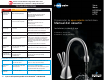

Scalding Hazard: The faucet dispenses near-boiling
(212ºF) water which can instantly cause scalds or
burns. Use care when operating this appliance.
Property Damage: Join remaining tube
to cold water supply only.
Property Damage: Join remaining tube
to cold water supply only.
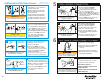
B
■
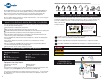
Turn on the cold water supply.
■ Depress
the dispenser’s HOT handle
and hold it until water flows from
the spout.
■
Run the water for at least 2 minutes to
flush lines (both the hot and cold handles
independently if applicable).
A
A
6
■
Check all connections to ensure they are
tight
and that there are no leaks.
■
Plug in instant hot water tank.
Water will be cold at first.
Allow 12-15 minutes for water to reach
target temperature.
Gurgling or hissing is normal during the
initial heating cycle.
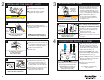
5
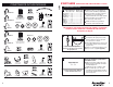
■
Install a T-fitting (not included)
onto the cold water supply line.
■
Install dedicated water control valve
with 3/8" compression fitting.
■
At the end of the white 3/8" tube from the
quick-connector, slide the supplied brass
nut and ferrule over the tube and then push
in the brass tube insert.
■
Insert the white 3/8" tube into the 3/8"
compression fitting and tighten.
HC-View/HC-Wave / HC3
■
Install a T-fitting (not included)
onto the cold water supply line.
■
Install dedicated water control valve
with 1/4" compression fitting.
■
At the end of the copper 1/4" tube,
slide the fitting’s brass nut and ferrule
over the tube.
■
Insert the copper tube into the 1/4"
compression fitting and tighten.
H-View / H-Wave / GN3/H990 / H770
A
Property Damage: A standard grounded outlet within
30" of the dispenser is required under the sink. Do
not use an extension cord set with the dispenser.
FINAL WATER CONNECTION
FILL TANK & THEN CONNECT POWER
Brass Nut
Plastic
tube
Ferrule
Brass Insert
tube
Copper
Brass Nut
Ferrule
Discharge
tube
From water
supply line
To dispenser
Property Damage: Do not extend the copper
lines farther than the 16" provided.
Personal Injury: Do not locate filter above an outlet or other
electrical device. Install head and bracket so that connections
require no stretching, kinking or pinching of tubing.
It is normal for approximately 2 oz. of water to
discharge when filter is removed.
Property Damage: Tube runs need to form to the cabinet’s
contours to allow storage space with no sharp bends. Tubes
need clean, perpendicular, burr-free cuts to ensure a true fit.
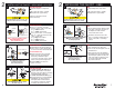
INSTALLING FILTRATION (Optional)
A
B
■ Determine length of tubing required,
then cut to length making sure the
cut is perpendicular and burr-free.
■ Insert a white 3/8" tube into inlet
side of filter head until it stops.
Press in again to ensure a secure fit.
■ Insert the other white 3/8" tube
into outlet side of filter head
until it stops. Press in again to
ensure a secure fit.
■ Mark hole locations for filter head
and bracket in a spot that allows
for filter replacement.
■ Drill 1/8" starter holes and attach
bracket to wall with wood screws,
turning until snug.
■ Remove red filter cap, insert filter
cartridge into filter head and twist
clockwise until “LOCK” arrow on the
filter aligns with arrow on bracket.
■ To redirect filter replacement water
discharge, place 6" clear tube over
vent hole on the left side of filter head.
■ Note: 3/8" fitting is required to make
connection to water supply.
■ Connect remaining white 3/8" tube
to incoming water supply line.
(See Step 5.)
C
■ Insert the copper tube(s) from the
dispenser into the 3/8" to 1/4"
quick-connect fitting.
■ Connect the white 3/8" tube
from the right outlet on the filter
head into the quick-connect fitting
until it stops. Press in again to
ensure a secure fit.
Available as an option;
separate purchase required.
from water
supply line
to dispenser
To remove tube(s) or plug from quick-connector,
depress the release ring and gently pull away.
From filter
H-View/H-Wave
GN3/H990/H770
From filter
D
HC-View
HC-Wave
HC3
Plug
10
11