
Radar Detector User Manual
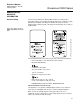

Reference Manual
00809-0100-4811, Rev CA
February 2006
Rosemount 3300 Series
B-12
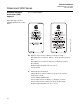
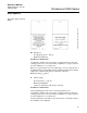
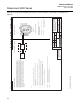
Figure B-12. System Control Drawing for hazardous location installation of intrinsically safe FM approved
apparatus.
FM Approved Product
No revisions to this drawing
without prior Factory Mutual
Approval.
SME-2917 01391
ISSUE CH. ORDER No WEEK
ISSUE CH. ORDER No WEEK ISSUE CH. ORDER No WEEK ISSUE CH. ORDER No WEEK
A3ORIGINAL SIZE
GU-LN
0139
3300
GU-PO 6 PDF
9150 077-944
9150 077-944
0139
SYSTEM CONTROL DRAWING
for hazardous location installation of Intrinsically
Safe FM approved apparatus
1
1/1
ISSUED BY
APPROVED BY
WEEK
WEEK
PRODUCT CODE
DOC. TYPE FILE
TITLE
DWG NO. ISSUE SHEET
SCALE
2:1
1 ST ANGLE
FINISH, UNLESS
OTHERWISE STATED:
ALL DIMENSIONS ARE IN MILLIMETRES.
T h e c o p y right/ownership of this document is and will remain ours.
T h e d o c u ment must not be used without our authorization or brought
to the knowledge of a third party. Contravention will be prosecuted.
Sa a b Marine Electronics AB, Sweden
ACCOCIATED APPARATUS
BARRIER
POWER
SUPPLY
ROSEMOUNT 3300 SERIES
Intrinsically Safe Apparatus for use in Class I, II, III,
Division 1, Groups A, B, C, D, E, F, G
Class I, Zone 0, AEx ia IIC T4
Temperature class : T4 (-40 <= Ta <= 70 deg C)
Entity Parameters : Vmax(Ui) <= 30 V, Imax(Ii) <= 130 mA
Ci=0nF,Li=0uH,Pi<=1W
HAZARDOUS LOCATION
NON-HAZARDOUS LOCATION
ENTITY CONCEPT APPROVAL
The Entity concept allows interconnection of intrinsically safe apparatus to associated apparatus
not specifically examined in combination as a system. The approved values of max. open circuit
voltage (Voc or Vt) and max. short circuit current (Isc or It) and max. power (Voc x Isc / 4) or (Vt x It / 4),
for the associated apparatus must be less than or equal to the maximum safe input voltage ( Vmax),
maximum safe input current (Imax), and maximum safe input power (Pmax) of the intrinsically safe
apparatus. In addition, the approved max. allowable connected capacitance (Ca or Co) of the associated
apparatus must be greater than the sum of the interconnecting cable capacitance and the unprotected
internal capacitance (Ci) of the intrinsically safe apparatus, and the the approved max. allowable
connected inductance (La or Lo) of the associated apparatus must be greater than the sum of the
interconnecting cable inductance and the unprotected internal inductance (Li) of the intrinsically
safe apparatus.
Notes:
1. No revision to this drawing without prior Factory Mutual approval.
2. Associated apparatus manufacturer's installation drawing muste be followed when
installing this product.
3. Dust-Tigth seal must be used when installed in Class II and Class III environments.
4. Control equipment connected to the barrier must not use or generate more than 250 Vrms or Vdc.
5. Resistance between Intrinsically Safe Ground and Earth Ground must be less than 1.0 ohm.
6. Installations should be in accordance with ANSI/ISA-RP12.6 "Installation of Intrinsically Safe
Systems for Hazardous Locations" and the National Electric Code (ANSI/NFPA 70).
7. The associated apparatus must be Factory Mutual Approved.
WARNING : To prevent ignition of flammable or combustible atmospheres,read , understand and adhere to the
manufacturer's live maintenance procedures.
WARNING: Substitution of components may impair Intrinsic Safety.
APPROVALS/077-944_1.EPS