Reference Manual 00809-0100-4811, Rev CA February 2006 Rosemount 3300 Series Guided Wave Radar Level and Interface Transmitters www.rosemount.
Reference Manual 00809-0100-4811, Rev CA February 2006 Rosemount 3300 Series Rosemount 3300 Series Guided Wave Radar Level and Interface Transmitters NOTICE Read this manual before working with the product. For personal and system safety, and for optimum product performance, make sure you thoroughly understand the contents before installing, using, or maintaining this product. Within the United States, Rosemount Inc. has two toll-free assistance numbers. Customer Central: 1-800-999-9307(7:00 a.m.
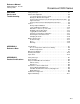
Reference Manual 00809-0100-4811, Rev CA February 2006 Rosemount 3300 Series Table of Contents SECTION 1 Introduction Safety Messages . . . . . . . . . . . . . . . . . . . . . . . . . . . . . . . . . . . . . . . . . 1-1 Manual Overview . . . . . . . . . . . . . . . . . . . . . . . . . . . . . . . . . . . . . . . . . 1-2 Service Support . . . . . . . . . . . . . . . . . . . . . . . . . . . . . . . . . . . . . . . . . . 1-3 SECTION 2 Transmitter Overview Theory of Operation. . . . . . . . . . . . . . . .
Reference Manual Rosemount 3300 Series 00809-0100-4811, Rev CA February 2006 Non-Intrinsically Safe Output . . . . . . . . . . . . . . . . . . . . . . . . . . . . 3-24 Intrinsically Safe Output . . . . . . . . . . . . . . . . . . . . . . . . . . . . . . . . 3-25 Optional Devices . . . . . . . . . . . . . . . . . . . . . . . . . . . . . . . . . . . . . . . . 3-26 Tri-Loop . . . . . . . . . . . . . . . . . . . . . . . . . . . . . . . . . . . . . . . . . . . .
Reference Manual 00809-0100-4811, Rev CA February 2006 Rosemount 3300 Series SECTION 6 Service and Troubleshooting Safety messages . . . . . . . . . . . . . . . . . . . . . . . . . . . . . . . . . . . . . . . . . 6-1 Advanced Configuration . . . . . . . . . . . . . . . . . . . . . . . . . . . . . . . . . . . 6-2 User defined Upper Reference Point . . . . . . . . . . . . . . . . . . . . . . . 6-2 Plotting the Measurement Signal . . . . . . . . . . . . . . . . . . . . . . . . . .
Reference Manual Rosemount 3300 Series TOC-4 00809-0100-4811, Rev CA February 2006
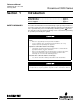
Reference Manual 00809-0100-4811, Rev CA February 2006 Section 1 Rosemount 3300 Series Introduction Safety Messages . . . . . . . . . . . . . . . . . . . . . . . . . . . . . . . . . page 1-1 Manual Overview . . . . . . . . . . . . . . . . . . . . . . . . . . . . . . . . page 1-2 Service Support . . . . . . . . . . . . . . . . . . . . . . . . . . . . . . . . .
Reference Manual Rosemount 3300 Series MANUAL OVERVIEW 00809-0100-4811, Rev CA February 2006 This manual provides installation, configuration and maintenance information for the Rosemount 3300 Series Radar Transmitter.
Reference Manual 00809-0100-4811, Rev CA February 2006 SERVICE SUPPORT Rosemount 3300 Series To expedite the return process outside of the United States, contact the nearest Rosemount representative. Within the United States, call the Rosemount National Response Center using the 1-800-654-RSMT (7768) toll-free number. This center, available 24 hours a day, will assist you with any needed information or materials.
Reference Manual Rosemount 3300 Series 1-4 00809-0100-4811, Rev CA February 2006
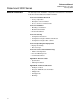
Reference Manual 00809-0100-4811, Rev CA February 2006 Section 2 Rosemount 3300 Series Transmitter Overview Theory of Operation . . . . . . . . . . . . . . . . . . . . . . . . . . . . . . page 2-1 Applications . . . . . . . . . . . . . . . . . . . . . . . . . . . . . . . . . . . . page 2-2 Components of the Transmitter . . . . . . . . . . . . . . . . . . . . page 2-4 System Architecture . . . . . . . . . . . . . . . . . . . . . . . . . . . . . . page 2-5 Probe Selection Guide . . . . . . . . . . . . . .
Reference Manual Rosemount 3300 Series APPLICATIONS 00809-0100-4811, Rev CA February 2006 The Rosemount 3300 Series Radar Transmitter program is suited for aggregate (total) level measurements on most liquids, semi-liquids, and liquid/liquid interfaces.
Reference Manual 00809-0100-4811, Rev CA February 2006 Rosemount 3300 Series APPLIC SEPARATOR APPLIC SEPARATOR Separator tank. The Rosemount 3302 measures both level and interface level. The Rosemount 3300 series is a good choice for underground tanks since it is installed on the tank top with the radar pulse concentrated near the probe. It can be equipped with probes that are unaffected by high and narrow openings or nearby objects.
Reference Manual 00809-0100-4811, Rev CA February 2006 Rosemount 3300 Series COMPONENTS OF THE TRANSMITTER The Rosemount 3300 Series Radar Transmitter has an aluminum transmitter housing which contains advanced electronics for signal processing. The radar electronics produces an electromagnetic pulse which is guided by the probe. There are different probe types available for various applications: Rigid Twin Lead, Flexible Twin Lead, Rigid Single Lead, Flexible Single Lead, and Coaxial. Figure 2-3.
Reference Manual 00809-0100-4811, Rev CA February 2006 SYSTEM ARCHITECTURE Rosemount 3300 Series The Rosemount 3300 Series Radar Transmitter is loop-powered which means it uses the same two wires for both power supply and output signal. The output is a 4-20 mA analog signal superimposed with a digital HART signal. By using the optional HART Tri-loop, it is possible to convert the HART signal to up to three additional 4-20 mA analog signals.
Reference Manual 00809-0100-4811, Rev CA February 2006 Rosemount 3300 Series PROBE SELECTION GUIDE Use the following guidelines to choose appropriate probe for your 3300 transmitter: Table 2-1. Probe selection guide.
Reference Manual 00809-0100-4811, Rev CA February 2006 Dead Zones Rosemount 3300 Series The measuring range depends on probe type and properties of the product. The Upper Dead Zone is the minimum measurement distance between the upper reference point and the product surface. The Upper Dead Zone varies between 4 - 20 in. (0.1 and 0.5 m) depending on probe type and product. At the end of the probe the measuring range is reduced by the Lower Dead Zone.
Reference Manual 00809-0100-4811, Rev CA February 2006 Rosemount 3300 Series PROCESS CHARACTERISTICS The Rosemount 3300 Series has a high sensitivity due to its advanced signal processing and high signal to noise ratio, which makes it able to handle various disturbances. However, the following circumstances should be considered before mounting the transmitter. Coating Coating on the probe should be avoided since the sensitivity of the transmitter may be decreased leading to measurement errors.
Reference Manual 00809-0100-4811, Rev CA February 2006 Rosemount 3300 Series Measuring Range The measuring range differs depending on probe type and characteristics of the application. The values given in Table 2-4 can be used as a guideline for clean liquids. Table 2-4. Measuring Range Coaxial Rigid Twin Lead Flexible Twin Lead Rigid Single Lead Flexible Single Lead Maximum Measuring Range 19 ft 8 in. (6 m) 9 ft 10 in. (3 m) 77 ft 1in. (23.5 m) 9 ft 10 in.
Reference Manual Rosemount 3300 Series 00809-0100-4811, Rev CA February 2006 For measuring the interface level, the transmitter uses the residual wave of the first reflection. Part of the wave, which was not reflected at the upper product surface, continues until it is reflected at the lower product surface. The speed of this wave depends fully on the dielectric constant of the upper product.
Reference Manual 00809-0100-4811, Rev CA February 2006 Rosemount 3300 Series Emulsion Layers Sometimes there is an emulsion layer (mix of the products) between the two products which, depending on its characteristics, will affect interface measurements. Please consult factory for guidelines on how to handle emulsion layers.
Reference Manual Rosemount 3300 Series 2-12 00809-0100-4811, Rev CA February 2006
Reference Manual 00809-0100-4811, Rev CA February 2006 Section 3 Rosemount 3300 Series Installation Safety messages . . . . . . . . . . . . . . . . . . . . . . . . . . . . . . . . . page 3-1 Installation Procedure . . . . . . . . . . . . . . . . . . . . . . . . . . . . page 3-3 Before You Install . . . . . . . . . . . . . . . . . . . . . . . . . . . . . . . . page 3-4 Mounting Considerations . . . . . . . . . . . . . . . . . . . . . . . . . page 3-6 Mechanical Installation . . . . . . . . . . . . . . . .
Reference Manual Rosemount 3300 Series 00809-0100-4811, Rev CA February 2006 High voltage that may be present on leads could cause electrical shock: Avoid contact with leads and terminals. Make sure the main power to the 3300 transmitter is off and the lines to any other external power source are disconnected or not powered while wiring the gauge. Probes covered with plastic and/or with plastic discs may generate an ignition-capable level of electrostatic charge under certain extreme conditions.
Reference Manual 00809-0100-4811, Rev CA February 2006 INSTALLATION PROCEDURE Rosemount 3300 Series Follow these steps for proper installation: Review Installation Considerations (see page 3-6) Check switches for 4-20 mA AlarmOutput (see page 3-4) Mount the transmitter (see page 3-13) Wire the transmitter (see page 3-21) Make sure covers and cable/conduit connections are tight.
Reference Manual 00809-0100-4811, Rev CA February 2006 Rosemount 3300 Series BEFORE YOU INSTALL Alarm and Write Protection Switches Electronic boards are electrostatically sensitive. Failure to observe proper handling precautions for static-sensitive components can result in damage to the electronic components. Do not remove the electronic boards from the 3300 Radar Transmitter.
Reference Manual 00809-0100-4811, Rev CA February 2006 Rosemount 3300 Series Figure 3-1. Switches for Alarm and Write Protection Alarm Output SWITCH WRP ALARM Write Protection To set the Alarm and Write Protect switches do the following: 1. Remove the cover on the circuit side (see main label). 2. To set the 4-20 mA alarm output to Low, move the Alarm switch to the LOW position. HIGH is the factory default setting (see Figure 3-1). 3.
Reference Manual Rosemount 3300 Series 00809-0100-4811, Rev CA February 2006 MOUNTING CONSIDERATIONS Before you install the Rosemount 3300 Series Radar Transmitter, be sure to consider specific mounting requirements, vessel characteristics and process characteristics. Process Connection The 3300 Series has a threaded connection for easy mounting on the tank roof. It can also be mounted on a nozzle by using different flanges. Threaded Connection Figure 3-2.
Reference Manual 00809-0100-4811, Rev CA February 2006 Rosemount 3300 Series Flange Connection on Nozzles Figure 3-3. Mounting in nozzles UNZ H NO_REDUCER/NOZZLE MOUNT V3 H D2=min. diameter with Upper Null Zone adjustment D1=min. diameter Avoid nozzles with reducer The transmitter can be mounted in nozzles by using an appropriate flange. It is recommended that the nozzle size is within the dimensions given in Table 3-4.
Reference Manual Rosemount 3300 Series Installation of Single Lead Probes in Non-metallic Tanks 00809-0100-4811, Rev CA February 2006 For optimal single lead probe performance in non-metallic tanks the probe must be mounted with a metal flange, or screwed in to a metal sheet (d>8 in./200 mm) if the threaded version is used. Figure 3-4. Mounting in non-metallic tanks. Metal sheet Ø>8”/200 mm NON-METAL_METALSHEET/NON-METAL_FLANGE Metal flange Ø>2”/DN50 Avoid disturbing EMC environment near the tank.
Reference Manual 00809-0100-4811, Rev CA February 2006 Rosemount 3300 Series Mounting in Still pipes/by-pass pipes In order to prevent the probe from contacting the bridle wall when replacing displacers or installing in pipes, centering discs are available for the Rigid Single, Flexible Single and Flexible Twin Lead probes. The disc is attached to the end of the probe and thus keeps the probe centered in the bridle. The discs are available in stainless steel and teflon (PTFE).
Reference Manual 00809-0100-4811, Rev CA February 2006 Rosemount 3300 Series Free Space For easy access to the transmitter make sure that it is mounted with sufficient service space. For maximum measurement performance the transmitter should not be mounted too close to the tank wall or other objects in the tank. If the probe is mounted close to a wall, nozzle or other tank obstruction noise might appear in the level signal.
Reference Manual 00809-0100-4811, Rev CA February 2006 Recommended Mounting Position Rosemount 3300 Series When finding an appropriate mounting position for the transmitter the conditions of the tank must be carefully considered. The transmitter should be mounted so that the influence of disturbing objects is reduced to a minimum. In case of turbulence the probe may need to be anchored to the bottom. See “Mechanical Installation“ on page 3-13 for more information. Figure 3-7.
Reference Manual 00809-0100-4811, Rev CA February 2006 Rosemount 3300 Series Insulated Tanks For insulated tanks the permitted ambient temperature is limited above a certain process temperature. Limitations depend on the thickness of the tank insulation, see “Ambient Temperature“ on page A-6 for more information. Tank insulation INSULATEDTANK.EPS HTHP version Ambient Temperature °F (°C) Process Temperature °F (°C) 3-12 AMBIENT_PROC_TEMP.EPS Figure 3-8. Maximum ambient temperature vs.
Reference Manual 00809-0100-4811, Rev CA February 2006 MECHANICAL INSTALLATION Rosemount 3300 Series Mount the transmitter with flange on a nozzle on top of the tank. The transmitter can also be mounted on a threaded connection. Make sure only qualified personnel perform the installation. NOTE If you need to remove the transmitter head from the probe, make sure that the Process Seal is carefully protected from dust and water. See “Service“ on page 6-9 for further information. Figure 3-9.
Reference Manual 00809-0100-4811, Rev CA February 2006 Rosemount 3300 Series Figure 3-11. Threaded tank connection. TRANSMITTER_MOUNT_THREAD.EPS 1. For tank connections with BSP/G threads, place a gasket on top of the tank flange, or use a sealant on the threads of the tank connection. Nut Tank connection Probe Sealant on threads or gasket (for BSP/G threads) 2. Lower the transmitter and probe into the tank. 3. Screw the adapter into the process connection. 4.
Reference Manual 00809-0100-4811, Rev CA February 2006 Rosemount 3300 Series Shortening the Probe Flexible Twin/Single Lead 1. Mark off the required probe length. Add at least 1.6 inch/40 mm to the required probe length to be inserted into the weight. 2. Loosen the Allen screws. 3. Slide the weight upwards as much as needed in order to cut the probe. 4. Cut the probe. If necessary, remove a spacer to make room for the weight. Minimum: 1.6 inch/ 40 mm 6. Tighten the screws. Spacer FLEX TWIN SHORT3 5.
Reference Manual 00809-0100-4811, Rev CA February 2006 Rosemount 3300 Series Rigid Twin Lead The spacers are put closer together at the probe end. The maximum amount that can be cut away is related to the ordering length L. To cut a Rigid Twin Lead probe do the following: RIGIDTWIN_SHORT_BA.EPS L>46.5 in. (1180 mm) 1. Cut the rods to the desired length: Max. shortening length: 19.7 in. / 500 mm • For probe length 20.5 to 46.5 in. (520 to 1180 mm) the minimium length is 20.5 in. (520 mm).
Reference Manual 00809-0100-4811, Rev CA February 2006 Rosemount 3300 Series Coaxial To cut a coaxial probe do the following: Centering piece NOTE! The HTHP coaxial probe must not be cut in field. COAXIAL_CUT.TIF 1. Insert the centering piece. (The centering piece is delivered from factory and should be used to prevent the spacers centering the rod from coming loose). 2. Cut the tube to the desired length. 3. Move the centering piece. 4. Cut the rod inside the tube.
Reference Manual Rosemount 3300 Series Anchoring 00809-0100-4811, Rev CA February 2006 In turbulent tanks it may be necessary to fix the probe. Depending on the probe type different methods can be used to guide the probe to the tank bottom. This may be needed in order to prevent the probe from hitting the tank wall or other objects in the tank, as well as preventing a probe from breaking. PROBEANCHOR RING FLEXIBLE TWIN Flexible Twin/Single Lead probe with weight and ring.
Reference Manual 00809-0100-4811, Rev CA February 2006 Rosemount 3300 Series Coaxial probe. PROBE SUPPORT2 COAX The Coaxial probe can be guided by a tube welded on the tank bottom. Tubes are customer supplied. Make sure that the probe can move freely in order to handle thermal expansion. Drain Rigid Twin Lead probe. PROBEANCHOR RIGID TWIN The Rigid Twin Lead probe can be secured to the tank wall by cutting the center rod and putting a fixture at the end of the outer rod.
Reference Manual 00809-0100-4811, Rev CA February 2006 Rosemount 3300 Series Mounting a Centering Disc for Pipe Installations Flexible Single/Twin Lead probe Centering disc 1. Mount the centering disc at the end of the weight. Tab washer Weight 2. Make sure that the tab washer is properly inserted in the centering disc. 3. Fasten the centering disc with the bolt. Bolt 4. Secure the bolt by folding the tab washer.
Reference Manual 00809-0100-4811, Rev CA February 2006 Rosemount 3300 Series ELECTRICAL INSTALLATION Cable/conduit entries The electronics housing has two entries for ½ - 14 NPT. Optional M20×1.5 and PG 13.5 adapters are also available. The connections are made in accordance with local or plant electrical codes. Make sure that unused ports are properly sealed to prevent moisture or other contamination from entering the terminal block compartment of the electronics housing.
Reference Manual Rosemount 3300 Series Power Requirements 00809-0100-4811, Rev CA February 2006 Terminals in the transmitter housing provide connections for signal cables. The 3300 transmitter is loop-powered and operates with power supplies ranging from 11 to 42 VDC. For Intrinsically Safe output the supply voltage must be within 11 to 30 VDC. For Explosion-proof/Flame-proof the supply voltage must be within 16 to 42 VDC.
Reference Manual 00809-0100-4811, Rev CA February 2006 The 3300 Series is a two-wire loop powered transmitter accepting power supplies ranging from 11 VDC to 42 VDC. It uses 4-20 mA power superimposed with a HART signal. To connect the transmitter: 1. Make sure that the power supply is disconnected. 2. Remove the cover on the transmitter housing terminal side (see label). Cable entry CONNECT_TRANSMITTER.EPS Connecting the Transmitter Rosemount 3300 Series 3.
Reference Manual 00809-0100-4811, Rev CA February 2006 Rosemount 3300 Series Non-Intrinsically Safe Output For non-intrinsically safe installations, wire the transmitter as shown in Figure 3-15. NOTE! Make sure that the power supply is off when connecting the transmitter. Figure 3-15. Wiring diagram for non-intrinsically safe installations.
Reference Manual 00809-0100-4811, Rev CA February 2006 Intrinsically Safe Output Rosemount 3300 Series For intrinsically safe installations wire the transmitter as shown in Figure 3-16. NOTE! Make sure that the instruments in the loop are installed in accordance with intrinsically safe field wiring practices and System Control Drawings when applicable. Figure 3-16.
Reference Manual 00809-0100-4811, Rev CA February 2006 Rosemount 3300 Series OPTIONAL DEVICES Tri-Loop The Model 3300 transmitter outputs a HART signal with four process variables. By using the Model 333 HART Tri-Loop up to three additional analog 4-20 mA outputs are provided. Figure 3-17.
Reference Manual 00809-0100-4811, Rev CA February 2006 Using More than one transmitter on the bus Rosemount 3300 Series The 3300 transmitter can be run in multidrop mode. In the multidrop mode each transmitter has a unique HART address. MULTIDROP Figure 3-18. Multidrop connection The poll address can be changed by using a 375 Field Communicator or by using the Rosemount Configuration Tools software. To change the poll address using a 375 Field Communicator choose HART command [1, 4, 5, 2, 1].
Reference Manual 00809-0100-4811, Rev CA February 2006 Rosemount 3300 Series 751 Field Signal Indicator Figure 3-19. Wiring diagram for 3300 transmitter with 751 Field Signal Indicator MODEL 3300 RADAR TRANSMITTER WIRING_751.EPS Model 751 Field Signal Indicator Power supply Figure 3-20. Alternative wiring diagram for 3300 transmitter with 751 Field Signal Indicator MODEL 3300 RADAR TRANSMITTER Model 751 Field Signal Indicator 3-28 WIRING_751_ALTERNATIVE.
Reference Manual 00809-0100-4811, Rev CA February 2006 Section 4 Rosemount 3300 Series Start-Up Safety messages . . . . . . . . . . . . . . . . . . . . . . . . . . . . . . . . . page 4-1 Configuration Parameters . . . . . . . . . . . . . . . . . . . . . . . . . page 4-2 Configuration using a 375 Field Communicator . . . . . . . page 4-7 Configuration using The Radar Configuration Tool . . . . page 4-14 Special Functions . . . . . . . . . . . . . . . . . . . . . . . . . . . . . . . .
Reference Manual 00809-0100-4811, Rev CA February 2006 Rosemount 3300 Series CONFIGURATION PARAMETERS The Rosemount 3301 transmitter can be configured for level and volume measurements. The Rosemount 3302 is designed to measure interface level and interface distance as well. The 3300 transmitter can be pre-configured according to the ordering specifications in the Configuration Data Sheet. Basic Configuration The basic transmitter configuration includes setting the tank geometry parameters.
Reference Manual 00809-0100-4811, Rev CA February 2006 Rosemount 3300 Series Reference Gauge Height The Reference Gauge Height is the distance from the Upper Reference Point to the bottom of the tank. The transmitter measures the distance to the product surface and subtracts this value from the Reference Gauge Height to determine the level. Probe Length The probe length is the distance between the Upper Reference Point and the end of the probe.
Reference Manual Rosemount 3300 Series 00809-0100-4811, Rev CA February 2006 Upper Null Zone This parameter should only be changed if there are measurement problems in the upper part of the tank. Such problems may occur if there are disturbing objects close to the probe. By setting the Upper Null Zone the measuring range is reduced. See Section 6: Disturbances at the Top of the Tank for further information. 4 mA point The 4 mA point should be set above the Lower Dead Zone (see Section 2: Dead Zones).
Reference Manual 00809-0100-4811, Rev CA February 2006 Volume Configuration Rosemount 3300 Series For volume calculations you can choose one of the standard tank shapes or the strapping option. Choose None if volume calculation is not used.
Reference Manual 00809-0100-4811, Rev CA February 2006 Rosemount 3300 Series Standard Tank Shapes Figure 4-4. Standard tank shapes Vertical Cylinder VERTICAL CYLINDER Vertical Cylinder tanks are specified by Diameter and Height. Diameter Height HORIZONTAL CYLINDER Horizontal Cylinder Horizontal Cylinders are specified by Diameter and Height. Diameter Height Vertical Bullet Height VERTICAL BULLET Diameter Vertical Bullet tanks are specified by Diameter and Height.
Reference Manual 00809-0100-4811, Rev CA February 2006 CONFIGURATION USING A 375 FIELD COMMUNICATOR Rosemount 3300 Series This section describes how to configure the 3300 transmitter by using a 375 Field Communicator. A 275 HART Communicator may also be used. For information on all the capabilities, refer to the 375 Field Communicator Product Manual (document 00809-0100-4276). Figure 4-5. The 375 Field Communicator.
Reference Manual 00809-0100-4811, Rev CA February 2006 Rosemount 3300 Series Figure 4-6. HART Communicator Menu Tree corresponding to Device Revision 2.
Reference Manual 00809-0100-4811, Rev CA February 2006 BASIC CONFIGURATION Rosemount 3300 Series This section describes the various HART commands used to configure the 3300 Series of transmitters for level measurements. The transmitter outputs a 4 - 20 mA signal proportional to the primary variable. Three additional variables are available through the HART signal. Transmitter Variables HART Comm 1, 1, 1, 1 You may assign up to four transmitter variables.
Reference Manual Rosemount 3300 Series 00809-0100-4811, Rev CA February 2006 Probe Type HART Comm 1, 3, 2, 3 The transmitter automatically makes an initial calibration based on the type of probe that is used. This parameter is pre-configured at factory and only needs to be set if the probe is changed to another type.
Reference Manual 00809-0100-4811, Rev CA February 2006 Rosemount 3300 Series Measurement Mode HART Comm 1, 3, 3, 4 Normally the Measurement Mode does not need to be changed. The transmitter is pre-configured according to the specified model: Table 4-1.
Reference Manual 00809-0100-4811, Rev CA February 2006 Rosemount 3300 Series 4 and 20 mA Points HART Comm 1, 3, 4, 3 When setting the range values, it is possible to enter the values directly using the keypad on the Field Communicator, or you may use actual values (HART command [1, 3, 4, 2]). Keep in mind that the 20 mA value should be below the Upper Dead Zone. If the 20 mA point is set to a point within the Dead Zone the full range of the analog output is not used.
Reference Manual 00809-0100-4811, Rev CA February 2006 Rosemount 3300 Series VOLUME CONFIGURATION Transmitter Variables HART Comm 1, 1, 1, 1 Select the Volume option in order to configure the transmitter for volume measurements.
Reference Manual 00809-0100-4811, Rev CA February 2006 Rosemount 3300 Series CONFIGURATION USING THE RADAR CONFIGURATION TOOL Installing the RCT software The Radar Configuration Tool (RCT) is a user-friendly software tool that allows you to configure the Rosemount 3300 transmitter. You can choose either of the following two methods to configure a 3300 transmitter: • Start the Wizard for a guided installation if you are unfamiliar with the Rosemount 3300.
Reference Manual 00809-0100-4811, Rev CA February 2006 Rosemount 3300 Series Figure 4-8. RHCS Server window RCT-RHCS_SERVER Check that the selected COM port matches the connected port on the PC. 3. Check the COM port. 4. Choose the COM Port option that matches the COM Port connected to the transmitter. 5. If communication is intermittent, increase Busy Retries and Error Retries to 5 and 5 respectively. 6.
Reference Manual Rosemount 3300 Series Using the Setup Wizard 00809-0100-4811, Rev CA February 2006 To install a 3300 transmitter by using the installation Wizard do the following: Figure 4-9. RCT workspace 1. Start the RCT software. Basic 2. In the RCT workspace click the Wizard icon (make sure that the Basic section is open), or choose the View>Wizard menu option. RCT1 Wizard Figure 4-10. RCT Wizard WIZARD WELCOME 3. Click the Start button and follow the instructions.
Reference Manual 00809-0100-4811, Rev CA February 2006 Using the Setup Function Rosemount 3300 Series To install a 3300 transmitter by using the Setup function do the following: Figure 4-11. RCT workspace 1. Start the RCT software. Basic 2. In the RCT workspace click the Setup icon (make sure that the Basic area is open), or choose the View>Setup menu option. RCT-RCT1 Setup Figure 4-12. Setup Info 3. Choose the appropriate tab: Info: information about the device.
Reference Manual Rosemount 3300 Series Setup - Info 00809-0100-4811, Rev CA February 2006 The Title tab shows information about the connected transmitter. RCT-SETUP_INFO Figure 4-13. Setup Title tab Device Name: designation of the current transmitter model. EPROM ID:current transmitter database version. Device Type: designates the transmitter type. 33 is used for the Rosemount 3300. Device ID: a unique identifier for each Rosemount 3300 Series transmitter.
Reference Manual 00809-0100-4811, Rev CA February 2006 Setup - Output Rosemount 3300 Series The Output tab lets you assign up to four transmitter variables. RCT-SETUP_OUTPUT Figure 4-15. Setup output tab Typically, the Primary Variable (PV) is configured to be Product Level, Interface Level or Volume. Other variables like Product Distance, Interface Distance, Upper Product Thickness, etc. are available as well. For the Rosemount 3301 the primary variable is typically set to be Level.
Reference Manual Rosemount 3300 Series Setup - Tank Config 00809-0100-4811, Rev CA February 2006 The Tank Configuration tab contains information on tank geometry parameters and dielectrics. RCT-SETUP_TANKCONF_V2.TIF Figure 4-16. Setup Tank Configuration tab Tank Geometry The Reference Gauge Height is the distance from the Upper Reference Point to the bottom of the tank (see Figure 4-1 on page 4-2).
Reference Manual 00809-0100-4811, Rev CA February 2006 Rosemount 3300 Series Measurement Mode Normally the Measurement Mode does not need to be changed. The transmitter is pre-configured according to the specified model: Table 4-2. Measurement Mode Model 3301 3302 Measurement Mode Level(1), Interface Immersed probe Level, Level and Interface(1), Interface Immersed probe (1) Default setting Interface Immersed Probe is used for applications where the probe is fully immersed in liquid.
Reference Manual 00809-0100-4811, Rev CA February 2006 Rosemount 3300 Series Measurements Below Probe End The Present Level=0... check box controls how the level value is presented when the tank is almost empty. By selecting this check box the Level is set equal to zero as long as the product surface is below the probe. LEVELBELOWPROBE.
Reference Manual 00809-0100-4811, Rev CA February 2006 Setup - LCD Rosemount 3300 Series The LCD tab lets you specify which parameters to appear on the display panel. The display has two rows, the upper row with five characters is for the measured value and the lower row with six characters for the value name. The display toggles between the different variables every 2 seconds. RCT-SETUP LCD Figure 4-18. Setup LCD tab Choose one of the following options: Table 4-3.
Reference Manual Rosemount 3300 Series 00809-0100-4811, Rev CA February 2006 SPECIAL FUNCTIONS TriLoop The Rosemount 333 HART Tri-Loop HART-to-Analog Signal Converter is capable of converting a digital HART burst signal into three additional 4-20 mA analog signals. To set the Rosemount 3300 transmitter up for the HART Tri-Loop do the following: 1. Make sure that the 3300 transmitter is properly configured. 2.
Reference Manual 00809-0100-4811, Rev CA February 2006 Rosemount 3300 Series 5. Set the 3300 in Burst mode. HART command [1, 4, 5, 2, 3]. RCT: Device Commands>Details>Set Burst Mode option. 6. Select Burst option 3=Process variables and current (Process vars/crnt). HART command [1,4,5,2,4]. 7. Install the Tri-Loop. Connect Channel 1 wires, and optionally wires for Channel 2 and Channel 3. 8. Configure Tri-Loop Channel 1: a. Assign variable: Tri-Loop HART command [1,2,2,1,1].
Reference Manual Rosemount 3300 Series 00809-0100-4811, Rev CA February 2006 To turn off the Burst Mode In order to turn off the Burst Mode use one of the following options: • The RCT program (requires that the Receive and Transfer Buffers for the selected COM Port is adjusted) • The Rosemount Burst Mode Switch software • A 375 Field Communicator • The AMS software To set the COM port buffers In order to be able to communicate with the 3300 in Burst Mode the Receive and Transfer Buffers need to b
Reference Manual 00809-0100-4811, Rev CA February 2006 Section 5 Rosemount 3300 Series Operating the Display Panel Display Functionality . . . . . . . . . . . . . . . . . . . . . . . . . . . . . page 5-1 Error Messages . . . . . . . . . . . . . . . . . . . . . . . . . . . . . . . . . . page 5-2 DISPLAY FUNCTIONALITY The Rosemount 3300 transmitter uses the display for presentation of measurement variables.
Reference Manual 00809-0100-4811, Rev CA February 2006 Rosemount 3300 Series ERROR MESSAGES The display can also be used for presentation of software errors. The upper row shows error codes and the lower row shows 'ERROR'. Figure 5-2.
Reference Manual 00809-0100-4811, Rev CA February 2006 Section 6 Rosemount 3300 Series Service and Troubleshooting Safety messages . . . . . . . . . . . . . . . . . . . . . . . . . . . . . . . . . page 6-1 Advanced Configuration . . . . . . . . . . . . . . . . . . . . . . . . . . page 6-2 Service . . . . . . . . . . . . . . . . . . . . . . . . . . . . . . . . . . . . . . . . . page 6-9 Diagnostic Messages . . . . . . . . . . . . . . . . . . . . . . . . . . . . .
Reference Manual 00809-0100-4811, Rev CA February 2006 Rosemount 3300 Series ADVANCED CONFIGURATION This section covers non-standard configuration. User defined Upper Reference Point If you want to specify your own Upper Reference Point you can do this by setting the Calibration Offset parameter. Figure 6-1. Tank Geometry Upper Reference Point Transmitter Reference Point Calibration Offset Product Level To set the desired upper reference point do the following: 1.
Reference Manual 00809-0100-4811, Rev CA February 2006 Rosemount 3300 Series Plotting the Measurement Signal The Radar Configuration Tool (RCT) has powerful tools for advanced troubleshooting. By using the Waveform Plot function you get an instant view of the tank signal. Measurement problems can be solved by studying the position and amplitude of the different pulses. To plot the measurement signal: 1. Start the Radar Configuration Tool program. 2.
Reference Manual 00809-0100-4811, Rev CA February 2006 Rosemount 3300 Series Logging and saving to disk The Waveform plot can be automatically logged and saved to file by specifying the read plot interval and the number of plots to log. WAVEFORM_PLOT_DISKLOG.TIF Figure 6-3. Disk logging Waveform plot Read action type Start monitoring Start disk logging Read plot interval Number of plots The Read Plot Interval entry field specifies the time interval between plots that are saved to disk.
Reference Manual 00809-0100-4811, Rev CA February 2006 Interface Measurements for Semi-Transparent Bottom Products Rosemount 3300 Series In interface applications where the bottom product has a low dielectric constant, or if the signal is attenuated in the upper product, the amplitude of the reflected signal is relatively low and difficult for the transmitter to detect. In such a case it may be possible to detect the reflected signal if the corresponding amplitude threshold is adjusted.
Reference Manual Rosemount 3300 Series 00809-0100-4811, Rev CA February 2006 Figure 6-4 illustrates a situation where amplitude threshold T3 is too high. The signal amplitude peak at the interface between the upper and lower products is not detected in this case.
Reference Manual 00809-0100-4811, Rev CA February 2006 High Level Rates Rosemount 3300 Series The measurement signal is filtered in order to minimize the influence of disturbing noise. In most measurement situations this does not have a noticeable effect on the response time to level changes. If high level rates occur it may however be necessary to reduce the damping value in order to allow the transmitter to respond quicker.
Reference Manual 00809-0100-4811, Rev CA February 2006 Rosemount 3300 Series Interface Measurements with Fully Immersed Probes The 3300 series has a measurement option which makes it possible to handle interface measurements when the product level is not visible, for example in a full bridle pipe as illustrated in Figure 6-6. In this case the probe is fully immersed into the upper product, and only the interface level is detected by the transmitter.
Reference Manual 00809-0100-4811, Rev CA February 2006 Rosemount 3300 Series SERVICE To calibrate the Analog Output current do the following: 1. Start RCT and make sure that the transmitter communicates with the PC (see Section 4: Installing the RCT software). 2. Open the Advanced section in the RCT workspace Project Bar and click the Device Commands icon, or choose the Device Commands option from the View menu. 3. Open the folder named Diag and double-click the Fixed Current Mode option.
Reference Manual 00809-0100-4811, Rev CA February 2006 Rosemount 3300 Series Level and Distance Calibration When calibrating the transmitter it is important that the product surface is calm and that the tank is not being filled or emptied. A complete calibration is performed in two steps: 1. Calibrate the Distance measurement by adjusting the Calibration Offset parameter. 2. Calibrate the Level measurement by adjusting the Reference Gauge Height. Distance calibration 1.
Reference Manual 00809-0100-4811, Rev CA February 2006 Disturbances at the Top of the Tank Rosemount 3300 Series Using the Trim Near Zone Function For transmitters using the Guided Wave Radar technology the performance In the Near Zone (referred to as the region between 0-1.6 ft (0-0.5 m) below the Upper Reference Point) is normally somewhat limited. However, the 3300 transmitter is equipped with software functionality that minimizes the Upper Dead Zone.
Reference Manual 00809-0100-4811, Rev CA February 2006 Rosemount 3300 Series To set the Upper Null Zone do one of the following: 1. Select the HART command [1, 3, 3, 1]. 2. Enter the desired value, or 1. Start the Radar Configuration Tool (RCT). 2. Click the Setup icon in the RCT workspace Project Bar. 3. Choose the Tank Config tab in the Setup window. 4. Click the Receive Page button. 5. Type the desired value in the Upper Null Zone field. 6. Click the Send Page button.
Reference Manual 00809-0100-4811, Rev CA February 2006 Amplitude Threshold Settings Rosemount 3300 Series The amplitude thresholds are automatically adjusted to appropriate values in order to filter out noise and other non-valid measurements from the measurement signal. The amplitude of the measurement signal, i.e. the amplitude of the signal that is reflected by the product surface, is related to the actual dielectric constant of the product.
Reference Manual 00809-0100-4811, Rev CA February 2006 Rosemount 3300 Series By adjusting the amplitude threshold T2 the product surface is detected correctly as illustrated in Figure 6-12. 100 80 P2 T3 After T2 is adjusted the product surface is correctly detected 200 60 Amplitude 250 40 T2 150 20 0 100 -20 T1 50 -40 P1 -60 0 0 100 200 300 400 500 600 Distance (samples) WAVEFORMPLOT THRESHOLD ADJUSTED Figure 6-12.
Reference Manual 00809-0100-4811, Rev CA February 2006 Rosemount 3300 Series Using the 375 Field Communicator To adjust amplitude threshold value: 1. Select HART command [1, 4, 5, 3]. The different amplitude thresholds appear on the display. Amplitude threshold 375_DISPLAY_THRESHOLDS.EPS Signal amplitude 375_DISPLAY_SET_THRESHOLDS.EPS 2. Open the desired amplitude threshold for editing. 3. Type the desired threshold value and click the ENTER button. 4.
Reference Manual 00809-0100-4811, Rev CA February 2006 Rosemount 3300 Series To start logging do the following: 1. Click the Monitor icon in the RCT workspace or choose the Monitor option from the View menu. RCT-MONITOR Logging Measurement Data Start monitoring Log interval Counter Start disk logging 2. Choose the desired variables to be monitored and click the Start Monitor button. Saving the log to disk 1. Choose the desired variables to be monitored. 2.
Reference Manual 00809-0100-4811, Rev CA February 2006 Saving the Transmitter Configuration Rosemount 3300 Series The Radar Configuration Tool offers different methods to save the current transmitter configuration: • Save only the configuration specified in the Setup window. • Use the more extensive function in the Memory Map window. You can use a stored configuration file as a backup of the current configuration, or it can be distributed for service purposes.
Reference Manual 00809-0100-4811, Rev CA February 2006 Rosemount 3300 Series To load a setup Open Setup RCT-SETUP_BASICS_SAVESETUP 1. Click the Setup icon in the RCT workspace or choose the Setup option from the File menu. 2. In the Setup window click the right mouse button and choose the Open Setup option, or from the File menu choose the Open Setup option. 3. Open the source folder and select the desired setup file. 4. Click the Open button.
Reference Manual 00809-0100-4811, Rev CA February 2006 Rosemount 3300 Series Removing the Transmitter Head 1. Loosen the nut that connects the transmitter housing to the Process Seal. FLANGE VERSION 2. Carefully lift the transmitter head. TRANSMITTER HOUSING REMOVE Nut Put the protection plug here! Process Seal 4. Attach the protection plug to the Process Seal. THREADED VERSION TRANSMITTER HOUSING THREAD REMOVE 3.
Reference Manual 00809-0100-4811, Rev CA February 2006 Rosemount 3300 Series Transmitter head Nut Process Seal Probe PROBE CHANGE FL_BA/PROBE CHANGE THREAD_BA Changing the Probe 1. Loosen the nut. 2. Remove the transmitter head from the old probe. 3. On the new probe, make sure that the protection plug is removed and the upper surface of the Process Seal is clean. Also make sure that the spring-loaded pin at the center of the Process Seal is properly inserted. 4.
Reference Manual 00809-0100-4811, Rev CA February 2006 Rosemount 3300 Series DIAGNOSTIC MESSAGES Troubleshooting If there is a malfunction despite the absence of diagnostic messages, see Table 6-1 for information on possible causes. Table 6-1. Troubleshooting chart Symptom No HART communication. Analog Out is set in Alarm. Both P2 and P3 are detected but Interface Level is reported as Not A Number (NAN) in the waveform plot. Both Level and Interface Level are reported as NAN.
Reference Manual 00809-0100-4811, Rev CA February 2006 Rosemount 3300 Series Errors Table 6-2 is a list of diagnostic messages that may be displayed on the Integral Display, on the 375 Field Communicator, in AMS Suite or by the Radar Configuration Tools (RCT) software. Errors normally result in Analog Output alarm.
Reference Manual 00809-0100-4811, Rev CA February 2006 Warnings Rosemount 3300 Series Table 6-3 is a list of diagnostic messages that may be displayed on the Integral Display, on the Model 375 Field Communicator or by the Radar Configuration Tools (RCT) software. Warnings are less serious than errors and in most cases do not result in Analog Output alarms. Warnings are indicated by a message at the bottom of the RCT workspace.
Reference Manual Rosemount 3300 Series 6-24 00809-0100-4811, Rev CA February 2006
Reference Manual 00809-0100-4811, Rev CA February 2006 Appendix A Rosemount 3300 Series Reference Data Specifications . . . . . . . . . . . . . . . . . . . . . . . . . . . . . . . . . . . page A-1 Dimensional drawings . . . . . . . . . . . . . . . . . . . . . . . . . . . . page A-7 Ordering Information . . . . . . . . . . . . . . . . . . . . . . . . . . . . . page A-12 Spare Parts . . . . . . . . . . . . . . . . . . . . . . . . . . . . . . . . . . . . .
Reference Manual Rosemount 3300 Series 00809-0100-4811, Rev CA February 2006 Mechanical Probes Tensile strength Collapse load Sideway capacity Material exposed to tank atmosphere Dimensions Probe angle Housing / Enclosure Flanges, Threads Height above flange Coaxial: 1.3 ft (0.4 m) to 19.7 ft (6 m). Rigid Twin Lead: 1.3 ft (0.4 m) to 9.8 ft (3 m). Flexible Twin Lead: 3.3 ft (1 m) to 77.1 ft (23.5 m). Rigid Single Lead: 1.3 ft (0.4 m) to 9.8 ft (3 m). Flexible Single Lead: 3.3 ft (1 m) to 77.1 ft (23.
Reference Manual 00809-0100-4811, Rev CA February 2006 Rosemount 3300 Series Measuring Performance Reference accuracy Repeatability Ambient Temperature Effect Update interval Measuring range (1) (2) (3) (4) ± 0.2 inch (5 mm) for probes ≤ 16.4 ft (5 m). ± 0.1% of measured distance for probes >16.4 ft (5 m). ± 0.04 inch (1 mm). Less than 0.01 % of measured distance per °C. 1 per second 16 inch (0.4 m) to 77 ft (23.5 m). PFA is a fluoropolymer with properties similar to PTFE. 1 mm PTFE cover.
Reference Manual 00809-0100-4811, Rev CA February 2006 Rosemount 3300 Series Process Temperature and Pressure Rating The tank connection consists of tank seal and a flange (EN, ANSI, Fisher or Masoneilan) or NPT or BSP/G threads (1 or 1.5 in. depending on probe type, see ”Ordering Information”.). Flange dimensions follows standard ANSI B 16.5 and EN 1092-1 type 05 (DIN 2527 type B) blind flanges if the transmitter is ordered with a flange.
Reference Manual 00809-0100-4811, Rev CA February 2006 Rosemount 3300 Series The HP and HTHP versions have a ceramic tank seal, and graphite gaskets no O-rings are used. The difference between the HP and HTHP versions is spacer material; PFA for HP, and ceramics for HTHP. Ceramic spacers allow for usage in applications with higher temperature. The following table gives the temperature ranges for tank seal with different O-ring material (applicable for the Standard Tank Connection): Table A-1.
Reference Manual Rosemount 3300 Series Ambient Temperature 00809-0100-4811, Rev CA February 2006 When the Rosemount 3300 is installed in high temperature applications, it is important that the maximum ambient temperature is considered. Tank insulation should not exceed 4 inches (10 cm). The diagram below shows the maximum ambient temperature vs.
Reference Manual 00809-0100-4811, Rev CA February 2006 Rosemount 3300 Series DIMENSIONAL DRAWINGS Figure A-5. Rigid Twin Lead NPT 1½ inch G 1½ inch 6.8 (173) ½ - 14 NPT Optional adapters: M20x1.5 PG13.5 NPT 1½ inch 6.8 (173) 4.1 (104) 4.3 (110) 4.3 (110) 4.5 (113) 9.6 (244) 9.6 (244) s60 L ≤ 10 feet (3 m) L ≤ 10 feet (3 m) Ø 0.31 (8) Ø 0.31 (8) Ø 0.24 (6) Ø 0.24 (6) 1.0 (25) 6.8 (173) s50 RIGID_TWIN_LEAD.EPS 1.8 (45) 1.1 (27) 1.0 (25) Flange 4.3 (110) 4.1 (104) 4.
Reference Manual 00809-0100-4811, Rev CA February 2006 Rosemount 3300 Series Figure A-6. Flexible Twin Lead NPT 1½ inch G 1½ inch 6.8 (173) 6.8 (173) ½ - 14 NPT Optional adapters: M20x1.5 PG13.5 NPT 1½ inch 4.3 (110) 4.1 (104) 4.3 (110) 4.5 (113) 9.6 (244) 9.6 (244) s60 1.8 (45) 1.1 (27) L ≤ 77 feet (23.5 m) s50 Ø 0.16 (4) Ø 0.16 (4) Ø 0.16 (4) Ø 0.16 (4) 3.5 (90) 3.5 (90) FLEX-TWIN-LEAD.EPS L ≤ 77 feet (23.5 m) 1.4 (35) 1.4 (35) 6.8 (173) Flange 4.1 (104) 4.3 (110) 4.
Reference Manual 00809-0100-4811, Rev CA February 2006 Rosemount 3300 Series Figure A-7. Coaxial NPT 1/1½ inch G 1/1½ inch 6.8 (173) ½ - 14 NPT Optional adapters: M20x1.5 PG13.5 NPT 1/1½ inch 6.8 (173) 4.3 (110) 4.1 (104) 4.3 (110) 4.5 (113) 9.5 (241) 9.5 (241) s52/s60 s52 2.4 (62) 1.1 (27) L ≤ 20 feet (6 m) COAXIAL.EPS L ≤ 20 feet (6 m) 1.1 (28) 1.1 (28) Flange 6.8 (173) 4.1 (104) 4.3 (110) HTHP/HP version 4.5 (113) 9.5 (241) For stainless steel, the probe is welded to the flange.
Reference Manual 00809-0100-4811, Rev CA February 2006 Rosemount 3300 Series Figure A-8. Flexible Single Lead G 1/1½ inch NPT 1/1½ inch 6.8 (173) ½ - 14 NPT Optional adapters: M20x1.5 PG13.5 NPT 1/1½ inch 6.8 (173) 4.3 (110) 4.1 (104) 4.3 (110) 4.5 (113) 9.5 (241) 9.5 (241) s52/s60 s52 L ≤ 77 feet (23.5 m) L ≤ 77 feet (23.5 m) FLEX-SINGLE-LEAD.EPS 2.4 (62) 1.1 (27) Ø 0.16 (4)/ Ø 0.28 (7) PTFE covered probe Ø 0.16 (4)/ Ø 0.28 (7) PTFE covered probe 5.5 (140)/ 17.
Reference Manual 00809-0100-4811, Rev CA February 2006 Rosemount 3300 Series Figure A-9. Rigid Single Lead G 1/1½ inch NPT 1/1½ inch 6.8 (173) ½ - 14 NPT Optional adapters: M20x1.5 PG13.5 NPT 1/1½ inch 6.8 (173) 4.3 (110) 4.1 (104) 4.3 (110) 4.5 (113) 9.5 (241) 9.5 (241) s52/s60 s52 2.4 (62) L ≤ 10 feet (3 m) L ≤ 10 feet (3 m) Ø 0.32 (8) Ø 0.47 (12) for the PTFE covered probe Ø 0.32 (8) Ø 0.47 (12) for the PTFE covered probe 6.8 (173) RIGID-SINGLE-LEAD.EPS 1.1 (27) Flange 4.1 (104) 4.
Reference Manual 00809-0100-4811, Rev CA February 2006 Rosemount 3300 Series ORDERING INFORMATION Model Code 3301, Level in Liquids Model Product Description 3301 Guided Wave Radar Level Transmitter (interface available for fully immersed probe) Code Signal Output H 4-20 mA with HART® communication Code Housing Material A Polyurethane-covered Aluminum Code Conduit / Cable Threads 1 ½ - 14 NPT 2 M20 x 1.5 adapter 3 PG 13.
Reference Manual 00809-0100-4811, Rev CA February 2006 Code Rosemount 3300 Series Process Connection - Size / Type (consult factory for other process connections) ANSI Flanges in 316L SST (ASME A182) AA 2 inch ANSI, 150 lb AB 2 inch ANSI, 300 lb AC 2 inch ANSI, 600 lb (HTHP / HP units) AD 2 inch ANSI, 900 lb (HTHP / HP units) AE 2 inch ANSI, 1500 lb (HTHP / HP units) BA 3 inch ANSI, 150 lb BB 3 inch ANSI, 300 lb BC 3 inch ANSI, 600 lb (HTHP / HP units) BD 3 inch ANSI, 900 lb (HTHP / HP
Reference Manual Rosemount 3300 Series 00809-0100-4811, Rev CA February 2006 Code Hazardous Locations Certifications NA E1 E5 E6 E7 I1 I5 I6 I7 KA KB KC KD KE KF No Hazardous Locations Certifications ATEX Flameproof FM Explosion Proof CSA Explosion Proof IECEx Flameproof ATEX Intrinsic Safety FM Intrinsic Safety and Non-Incendive CSA Intrinsic Safety and Non-Incendive IECEx Intrinsic Safety ATEX and CSA Flameproof/Explosionproof FM and CSA Explosionproof ATEX and FM Flameproof/Explosionproof ATEX and CS
Reference Manual 00809-0100-4811, Rev CA February 2006 Rosemount 3300 Series Model Code 3302, Level and Interface in Liquids Model Product Description 3302 Guided Wave Radar Level and Interface Transmitter Code Signal Output H 4-20 mA with HART® communication Code Housing Material A Polyurethane-covered Aluminum Code Conduit / Cable Threads 1 ½ - 14 NPT 2 M20 x 1.5 adapter 3 PG 13.
Reference Manual Rosemount 3300 Series Code Process Connection - Size / Type (consult factory for other process connections) ANSI Flanges in 316L SST (ASME A182) AA 2 inch ANSI, 150 lb AB 2 inch ANSI, 300 lb AC 2 inch ANSI, 600 lb (HTHP / HP units) AD 2 inch ANSI, 900 lb (HTHP / HP units) AE 2 inch ANSI, 1500 lb (HTHP / HP units) BA 3 inch ANSI, 150 lb BB 3 inch ANSI, 300 lb BC 3 inch ANSI, 600 lb (HTHP / HP units) BD 3 inch ANSI, 900 lb (HTHP / HP units) BE 3 inch ANSI, 1500 lb (HTHP / HP units) CA 4 in
Reference Manual 00809-0100-4811, Rev CA February 2006 Code Hazardous Locations Certifications NA E1 E5 E6 E7 I1 I5 I6 I7 KA KB KC KD KE KF No Hazardous Locations Certifications ATEX Flameproof FM Explosion Proof CSA Explosion Proof IECEx Flameproof ATEX Intrinsic Safety FM Intrinsic Safety and Non-Incendive CSA Intrinsic Safety and Non-Incendive IECEx Intrinsic Safety ATEX and CSA Flameproof/Explosionproof FM and CSA Explosionproof ATEX and FM Flameproof/Explosionproof ATEX and CSA Intrinsic Safety FM
Reference Manual Rosemount 3300 Series 00809-0100-4811, Rev CA February 2006 SPARE PARTS Spare parts list Transmitter head Model 3301/3302 Model Product Description 3301 Transmitter head Model 3301 3302 Transmitter head Model 3302 Code H Code A Code 1 2 3 Code N Code 0 Code N Code 9R 9F Code N Code 00 Code 00 Code NA E1 E5 E6 E7 I1 I5 I6 I7 KA KB KC KD KE KF A-18 Signal Output 4-20 mA with HART communication Housing Material Polyurethane-covered Aluminum Conduit Threads/Cable Threads ½ - 14 NPT M
Reference Manual 00809-0100-4811, Rev CA February 2006 Code Rosemount 3300 Series Options M1 Integral Digital Display BT Bar Code Tag T0 Terminal block without transient protection Cx - Special Configuration (Software) C1 Factory configuration (CDS required with order) C4 Namur alarm and saturation levels, high alarm C5 Namur alarm and saturation levels, low alarm C8 Low alarm(1) (standard Rosemount alarm and saturation levels) Cx - Special Certs Q4 Calibration Data Certification (1) The standard alar
Reference Manual 00809-0100-4811, Rev CA February 2006 Rosemount 3300 Series Spare parts list Probe Model 3301/3302 Model 3309 Product Description Spare probe Code Signal Output N Not applicable Code N Code 0 Code S H P Code 1 2 3 7 8 Code V E K B N Code Housing Material Not applicable Conduit Threads/Cable Threads Not applicable Operating Temperature and Pressure Standard: -15 psig (-1 Bar) to 580 psig (40 Bar) @ 302 °F (150 °C) (1) High Temp / High Pressure High Pressure Material of Construction:
Reference Manual 00809-0100-4811, Rev CA February 2006 Code Rosemount 3300 Series Process Connection - Size/Type (consult factory for other process connections) ANSI Flanges in ASME A182 Gr.
Reference Manual Rosemount 3300 Series Code Hazardous Locations Certifications NA Not applicable Code Options P1 N2 LS 00809-0100-4811, Rev CA February 2006 Hydrostatic testing NACE material recommendation per MR 01-75(1) Long Stud 9.8 in. (250 mm) for Flexible Single Lead probe. Prevents the wire from contacting wall/nozzle. Standard height is 3.9 in. (100 mm). CP Centering disc PTFE(2) CS Centering disc SST(2) Qx - Special Certs Q8 Material Traceability Certification per EN 10204 3.
Reference Manual 00809-0100-4811, Rev CA February 2006 Rosemount 3300 Series Spare parts list Other Spares and Accessories Model 3301/3302 Code Process Connection - Size/Type (consult factory for other process connections) Display kit and covers 03300-0670-0002 Integral Display Kit (including cover) 03300-0670-0001 Integral Display Kit (does not include cover) 03300-7002-0001 Integral Display Cover (long) 03300-7002-0002 Electronics cover 03300-7002-0003 O-ring for Electronics cover, Integral display co
Reference Manual Rosemount 3300 Series A-24 00809-0100-4811, Rev CA February 2006
Reference Manual 00809-0100-4811, Rev CA February 2006 Appendix B Rosemount 3300 Series Product Certifications Safety Messages . . . . . . . . . . . . . . . . . . . . . . . . . . . . . . . . . page B-1 EU Conformity . . . . . . . . . . . . . . . . . . . . . . . . . . . . . . . . . . . page B-2 European ATEX Directive Information . . . . . . . . . . . . . . . page B-3 Hazardous Locations Certifications . . . . . . . . . . . . . . . . . page B-5 Combination of Approvals . . . . . . . . . . . . . . . . . .
Reference Manual Rosemount 3300 Series 00809-0100-4811, Rev CA February 2006 High voltage that may be present on leads could cause electrical shock: Avoid contact with leads and terminals. Make sure the main power to the Radar Transmitter is off and the lines to any other external power source are disconnected or not powered while wiring the transmitter. Probes covered with plastic and/or with plastic discs may generate an ignition-capable level of electrostatic charge under certain extreme conditions.
Reference Manual 00809-0100-4811, Rev CA February 2006 Rosemount 3300 Series EUROPEAN ATEX DIRECTIVE INFORMATION Intrinsic Safety The Rosemount 3300 Series Guided Wave Radar Level and Interface Transmitter that has the following label attached has been certified to comply with Directive 94/9/EC of the European Parliament and the Council as published in the Official Journal of the European Communities No. L 100/1 on 19-April-1994. APPROVALS-ATEX_BAS_I1/NAMEPLATE Figure B-1.
Reference Manual Rosemount 3300 Series Flameproof 00809-0100-4811, Rev CA February 2006 The Rosemount 3300 Series Guided Wave Radar Level and Interface Transmitter that has the following label attached has been certified to comply with Directive 94/9/EC of the European Parliament and the Council as published in the Official Journal of the European Communities No. L 100/1 on 19-April-1994. APPROVALS-ATEX_KEMA_E1/NAMEPLATE Figure B-2.
Reference Manual 00809-0100-4811, Rev CA February 2006 Rosemount 3300 Series HAZARDOUS LOCATIONS CERTIFICATIONS The Rosemount 3300 Series Guided Wave Radar Level and Interface Transmitters that have the following labels attached have been certified to comply with the requirements of the approval agencies noted. Factory Mutual (FM) Approvals Project ID: 3013394 APPROVALS-FM_E5, FM_I5 Figure B-3.
Reference Manual Rosemount 3300 Series Canadian Standards Association (CSA) Approval 00809-0100-4811, Rev CA February 2006 Cert. no. 2002.1250250. APPROVALS-CSA_E6, CSA_I6 Figure B-4. Approval Label Canadian Standards Association (CSA) E6 Explosion-Proof for Class I, Division 1, Groups C and D. Dust-Ignition proof for Class II, Division 1 and 2, Groups G and Coal Dust. Dust-Ignition proof for Class III, Division 1, Hazardous Locations [Ex ia IIC T6]. Ambient temperature limits: -40°C to + 85°C.
Reference Manual 00809-0100-4811, Rev CA February 2006 Rosemount 3300 Series IECEx Approval APPROVALS-IECEX_E7.TIF, IECEX_I7.TIF Figure B-5. Approval Labels IECEx. E7 Flameproof: Ex d [ia] IIC T6 (Tamb = +60 °C). IECEx TSA 04.0013X. Conditions of Certification The apparatus metallic enclosure must be electrically bonded to earth. The conductor used for the connection shall be equivalent to a copper conductor of 4 mm2 minimum cross-sectional area.
Reference Manual Rosemount 3300 Series 00809-0100-4811, Rev CA February 2006 COMBINATION OF APPROVALS ATEX_CSA_E1_E6.TIF Figure B-6. Approval Label ATEX Flame-Proof and Canadian Standards Association (CSA) Explosion-Proof. FM_CSA_E5_E6.TIF Figure B-7. Approval Label CSA Explosion-Proof and FM Explosion-Proof.
Reference Manual 00809-0100-4811, Rev CA February 2006 Rosemount 3300 Series ATEX_FM_E1_E5.TIF Figure B-8. Approval Label ATEX Flame-Proof and FM Explosion-Proof. ATEX_CSA_I1_I6.TIF Figure B-9. Approval Label ATEX Intrinsic Safety and CSA Intrinsic Safety.
Reference Manual Rosemount 3300 Series 00809-0100-4811, Rev CA February 2006 FM_CSA_I5_I6.TIF Figure B-10. Approval Label FM Intrinsic Safety and CSA Intrinsic Safety. ATEX_FM_I1_I5.TIF Figure B-11. Approval Label ATEX Intrinsic Safety and FM Intrinsic Safety.
Reference Manual 00809-0100-4811, Rev CA February 2006 APPROVAL DRAWINGS Rosemount 3300 Series This section contains Factory Mutual installation drawings and Canadian Standards installation drawings. You must follow the installation guidelines presented in order to maintain certified ratings for installed transmitters.
B-12 0139 WEEK ALL DIMENSIONS ARE IN MILLIMETRES. 0139 6 1 ST ANGLE ISSUE CH. ORDER No WEEK ISSUE CH. ORDER No PDF 2:1 SCALE 1 ISSUE The copyright/ownership of this document is and will remain ours. The document must not be used without our authorization or brought to the knowledge of a third party. Contravention will be prosecuted. Saab Marine Electronics AB, Sweden 9150 077-944 DWG NO.
30V 30V C D 130 mA 130 mA 130 mA Ii (Imax) 0 nF 0 nF 0 nF Ci 0 uH 0 uH 0 uH Li 1W 1W 1W Pi EX-CERTIFIED PRODUCT. No modifications permitted without reference to the Ex-certifying Authorities. NOTE 3. NOTE 2. NOTE 1. 0213 6 GU-PO OrCAD FILE 1 ST ANGLE 1:1 SCALE FINISH, UNLESS OTHERWISE STATED: DOC. TYPE WEEK PRODUCT CODE WEEK 0213 3300 ISSUED BY APPROVED BY ALL DIMENSIONS ARE IN MILLIMETRES.
Reference Manual Rosemount 3300 Series 00809-0100-4811, Rev CA February 2006 9150077-991_I01_P01_A3 (CAL) COPY.EPS Figure B-14. System Control Drawing for hazardous location installation of IECEx approved apparatus.
Reference Manual 00809-0100-4811, Rev CA February 2006 Rosemount 3300 Series Index Numerics 20 mA point . . . . . . . . . 4-4, 275 HART Communicator . . . 375 Field Communicator . . . . 4 and 20 mA Points . . . . . . . 4 mA point . . . . . . . . . 4-4, 751 Field Signal Indicator . . . 4-19 . 4-7 . 4-7 4-12 4-19 3-28 A Agitators . . . . . . . . . . 2-11, 3-11 Alarm switch . . . . . . . . . . . . . 3-5 Amplitude Threshold Settings 6-13 Amplitude Thresholds . . . . . . . 6-3 AMS Suite . . . . . . . . . . .
Reference Manual 00809-0100-4811, Rev CA February 2006 Rosemount 3300 Series M Maximum load resistance 3-24, 3-25 Maximum Upper Product Thickness 4-11 Measurement Mode . . Measurement Principle Measurement Units . . Measuring range . . . . Memory Map . . . . . . . Mounting Position . . . Multidrop connection . Multidrop Mode . . . . . 4-11, 4-21 . . . . . . 2-1 . 4-9, 4-18 . . . . . . 2-9 . . . . . 6-18 . . . . . 3-11 . . . . . 3-27 . . . . . 3-27 N NAMUR-Compliant Alarm Non-metallic tanks . . . . .
Reference Manual 00809-0100-4811, Rev CA February 2006 Rosemount 3300 Series Rosemount and the Rosemount logotype are registered trademarks of Rosemount Inc. PlantWeb is a registered trademark of one of the Emerson Process Management group of companies. Teflon, VITON, and Kalrez are registered trademarks of DuPont Performance Elastomers. Asset Management Solutions is a trademark of Emerson Process Management. All other marks are the property of their respective owners.