
Data Sheet

YD and YS Valves
D100031X012
Product Bulletin
51.1:YD
June 2014
6
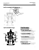
Plug Up, Right-Hand Port Closed--Flow in
converging service is from bottom to left port and
in diverging service is from left to bottom port.
Intermediate Plug Positions--Flow in converging
service is from both bottom and right ports to left
port, with capacities in proportion to plug travel.
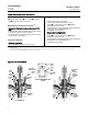
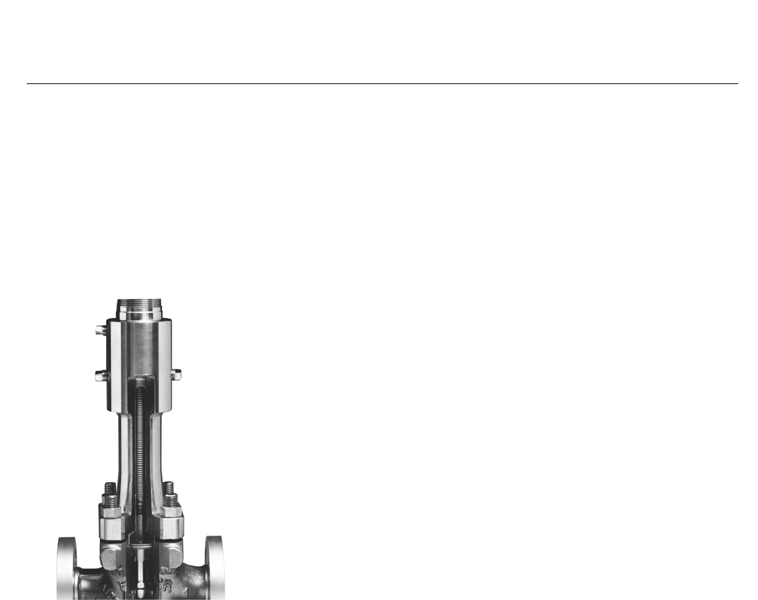
Figure 4. Cutaway of ENVIRO-SEAL Bellows Seal
Bonnet and Internal Shroud, Showing Bellows
W5852-1
ENVIRO-SEAL, HIGH-SEAL
Packing Systems
ENVIRO-SEAL and HIGH-SEAL packing systems offer
excellent sealing capabilities. These systems easily
install in your existing valves or can be purchased with
new valves. These systems help you seal your process
to conserve valuable process fluid. The long
operational life and reliability of these systems also
reduce your maintenance costs and downtime.
For applications requiring compliance with
environmental protection regulations, the unique
ENVIRO-SEAL packing system (figure 5) and, for
hazardous service, the ENVIRO-SEAL bellows seal
system (figure 4) are offered. The emission control
packing system keeps emission concentrations below
the EPA 100 ppm requirement.
For an excellent stem seal in applications that are not
environmentally sensitive, the HIGH-SEAL Graphite
ULF packing system (figure 5) is offered. The
HIGH-SEAL packing system provides excellent sealing
at pressure/temperature ratings beyond ENVIRO-SEAL
limits. ENVIRO-SEAL systems may also be applied for
excellent stem sealing in higher pressure/temperature
applications not requiring EPA compliance.
ENVIRO-SEAL packing systems, available with PTFE,
Graphite ULF, or Duplex packing, and the HIGH-SEAL
Graphite ULF packing system feature live-loading and
unique packing-ring arrangements for long-term,
consistent sealing performance.
Installation
Although YD and YS valves may be mounted with the
actuator in any position relative to the valve, the
normal position is with the valve in a horizontal run of
pipe and the actuator vertical above the valve. The
actuator should be supported in any position other
than vertical. Orient the valve so that valve plug
positions and flow directions will conform to the flow
indicator plate on the valve body.
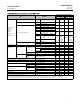
Dimensions are shown in figure 8.
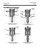
Note: For the NPS 8 high temperature construction,
thebottomflangeMUSTberemovedtoaccessand
remove the lower cage (see figure 2). BWE end
connections are not available for the NPS 8 high
temperature constructions for this reason.