
Instruction Manual

Instruction Manual
D101957X012
V150 and V300 Valves
November 2011
12
Disassembly
WARNING
When the actuator is removed from the valve, the ball may suddenly rotate, resulting in personal injury. To avoid injury,
carefully rotate the ball to a stable position.
Once the drive and follower shafts have been removed from the valve body, the ball may fall out of or into the valve body.
To avoid personal injury or damage to the sealing surfaces of the ball, provide a hoist to support the ball to prevent it from
falling as the shafts are being removed.
1. Carefully lift the valve and set it on the edge of the flanges so the ball is in the open position, and in the down
position. (Note: The weight of the ball should turn it into the open position.) Block the drive end of the valve body to
hold the shaft in a horizontal position.
2. Drive the pins (key 7) out of the drive shaft and out of the follower shaft (keys 6 and 9).
Both pins are tack welded to the ball ears. To remove a pin, insert a pin punch into the open hole, opposite the tack
welded side, and break the tack weld while driving the pin out.
3. Carefully lift the valve and place the valve on the working surface with the seal side down (read the Warning above).
Because of the weight of the ball, it should rotate so the contoured sealing surface of the ball is resting on the surface.
4. Remove the flange nuts (key 47), the bottom flange (key 44), and gasket (key 45) from the valve. Use a hoist to lift
valve body slightly.
Make sure the sealing surface of the ball is not damaged while removing the follower shaft (key 9).
5. Push the follower shaft (key 9) into the center of the ball. For valves with metal bearings, remove the thrust washer
(key 38).
6. Pull the drive shaft (key 6) out of the actuator side of the valve body. For valves with metal bearings, remove the
thrust washer (key 38).
7. Removing the bearings (key 10):
a. For PEEK bearings, remove the bearings by hand. If the bearings are tight in the valve body, pull or drive them out
with a slight pressure.
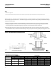
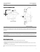
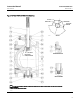
b. For metal bearings, use a press and ram to remove the drive shaft bearings out of the valve body. Refer to figure
7 for ram dimensions.
D To remove the follower shaft bearing from the bottom flange (key 44), use a blind-hole bearing puller similar to
CG2545AB, which is made by Snap-on Tools. If you do not have such a tool, you can machine the bearing out of the
bottom flange.
Note
For proper shutoff performance, the ball and seal require the bearing (key 10) to be positioned correctly. If you removed t he
bearings (key 10), be sure to locate t he new bearings as shown in figure 7.
8. Thoroughly clean all surfaces of parts that are to be re-used or obtain replacement parts. Upon reassembly, the pins
needs to be tack welded to the ball ears. Remove excess weld material, if the parts are to be used during
re-assembly.