
Instruction Manual


Basis Weight Actuator
23
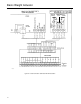
2. Record the location of the wire connections on the
terminal block. Remove the transformer wires from the
terminal block.
3. Unscrew the mounting screw from the center of the
transformer and remove the transformer from the back
of the cabinet.
4. Be sure to remove insulation from the ends of the
transformer wires.
5. Attach the new transformer and connect the trans-
former wires to the terminal block (see figure 9). Make
sure the jumper between TB2-7 and TB2-Ground is
installed.
6. Close the cabinet, turn on power, and check opera-
tion of the system before returning it to service.
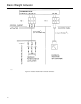
Field Installation of the Remote Station
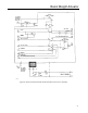
Follow these steps to install a Remote Station to an
already exisitng IC2000 unit. See figure 18.
1. The IC2000 has no 24Vdc for external units, but a
power outlet is included. So, a Rectifier Bridge is in-
cluded with the Remote Station.
2. Drill a 4.2 mm (0.165 inch) hole to the left of TB1.
Make a thread of 5mm and mount the Rectifier Bridge,
see figure 18.
3. Connect AC power input to the Rectifier from termi-
nals 10 and 11 on TB2. Be sure to connect on the up-
per side of the terminal after the terminal fuse.
4. Install the Remote Station. Install a junction box
close to the Remote Station.
5. Install a multi-wire cable with a screen, having at
least 9 wires between the IC2000 and the junction box.
Connect the wires as shown in figure 18.
6. Connect wires 1 and 9 without terminals directly to
the Rectifier. Use the end connectors provided.
7. Install a multi-wire cable with a screen between the
computer and the junction box (see figure 18). If the
status information is fed to the computer, the cable
must have at least 6 wires. Otherwise, 3 are needed.
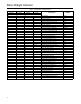
Parts List
A Fisher Controls serial number is assigned to each
basis weight control system. This serial number can be
found on a nameplate attached to the actuator mount-
ing yoke. Refer to this serial number whenever corre-
sponding with your Fisher Controls sales office or
sales representative about this equipment. When or-
dering replacement parts, also include the part number
from the Parts List section.
Description Part Number
IC2000 Control Cabinet 12B0720X012
IC500 Module 12B0723X012
FT100 module 12B0726X012
SD13 Card 12B0721X022
Limit Switch 11B9830X012
Transformer RTR 17401 10B6819X032
14 Pin female connector 11B9828X012
14 Pin male connector 11B9829X012
Terminal Block TB3 17B5977X012
Terminal Block TB4 17B5977X022
Remote Station 12B0725X012
Manual Station Module 12B0724X012
Extender Card 12B9361X012
Motor
Size 20HT 10B6807X032
Size 30HT & 40HT 10B6807X042
Handwheel
Size 20HT 13B7129X032
Size 30HT 13B7129X022
Size 40HT 13B7129X012
Housing Kit for Motor Coupling
Size 20HT 13B7129X062
Size 30HT 13B7129X052
Size 40HT 13B7129X042
Valve Position Indicator Assembly
2 Limit Switch 13B7130X012
4 Limit Switch 13B7130X022
Elastomer Spider for Motor Coupling
Size 20HT 17B7755X012
Size 30HT & 40HT 17B7755X022