
Instruction Manual


Instruction Manual
D103164X012
V150S Slurry Vee-Ball Valve
May 2012
9
11. Fit the spring (key 19), gasket (key 21), and plug (key 20).
For service applications involving scale formation that sets up and “freezes” mating parts, supplementary
recommendations for assembly can be provided by your Emerson Process Management sales office.
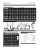
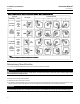
Actuator Mounting
Use the appropriate actuator instruction manual, this section of t his manual, and figure 8 of this manual when
mounting the actuator or changing actuator styles and positions.
1. To help ensure correct centering of the V-notch ball (key3)ontheflowring(key4or28/29),besuretheballis
closed when mounting the actuator (for applications other than Spring Return Fail-Open).
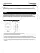
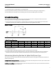
Figure 7. Pin Punch
D
0.010
B
A
C
R 0.010
MAX
E0878
Table 6. Pin Punch Dimensions
Valve Size, NPS
Ball Pin Hole Shaft Pin Hole
A
Min
B
Max
C
Max
D
Min
3and4 0.19 0.16 0.25 0.15 0.085 1.45
6 0.22 0.19 0.25 0.18 0.105 1.85
8and10 0.28 0.25 0.38 0.24 0.135 2.2
12 0.28 0.25 0.38 0.24 0.135 2.6
2. Clean the valve shaft and actuator lever splines to be sure the actuator lever will slide on easily. Only drive the lever
in if absolutely necessary.
3. Carefully wedge the ball solidly against the actuator-side bearing to center t he ball.
4. Keep the wedge in place while installing the lever, if necessary. Remove the wedge after you have clamped the
actuator lever on the valve shaft and have connected the lever to the actuator piston rod or diaphragm rod.
Determining Mounting Position for Spline Shaft/Lever Type
The actuator can be either right or left-hand mounted, with the actuator on the right or left side when viewed from
upstream (see figure 8).
For right-hand mounting (standard), the ball will be in the top of the valve body when the valve is open and the shaft is
horizontal.InthispositiontheballrotatesCWtoClose.
For left-hand mounting, theballwillbeinthetopofthevalvebodywhenthevalveisopenandtheshaftishorizontal.
In this position the ball rotates CCW to Close.