
Instruction Manual


Instruction Manual
D103164X012
V150S Slurry Vee-Ball Valve
May 2012
2
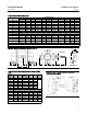
Table 1. Specifications
Valve Sizes and End Connection Styles
NPS J 3, J 4, J 6, J 8, J 10, and J 12 with CL150
raised-face flanges
Shutoff Classification
Construction does not provide tight shutoff. Nominal
gap between ball and flow ring seat is 0.035 inch for
high chrome iron construction and 0.015 inch for
ceramic insert construction.
Construction Materials
Standard Construction: See table 2
Flow Direction
Reverse flow recommended (into concave face of
ball, out through the flow ring)
Valve Installation
Shaft axis shall be horizontal
Actuator Mounting
Right-hand or left-hand, as viewed from upstream
end of valve
Maximum Ball Rotation
90 degrees
Valve/Actuator Action
With diaphragm or piston rotary actuator and splined
shaft, the valve is field-reversible between PDTC or
PDTO:
J push-down-to-close (extending actuator
rod closes valve) and
J push-down-to-open
(extending actuator rod opens valve)
Table 2. Standard Construction Materials
Part Material
Valve Body Carbon Steel ASTM A216 WCC
Body Liner High Chrome Iron ASTM A532 Class III Type A
V-notch Ball High Chrome Iron ASTM A532 Class III Type A
Flow Ring High Chrome Iron ASTM A532 Class III Type A
Flow Ring Insert type (optional) High Chrome Iron ASTM A532 Class III Type A
Flow Ring Retainer Carbon Steel ASTM A105
Bearing Shroud High Chrome Iron ASTM A532 Class III Type A
Bearing 440C 58Rc
Drive Shaft 17-4PH Cond. H1025
Follower Shaft 17-4PH Cond. H1025
Shaft Pins Carbon Steel, zinc plated
Spring Carbon Steel
Gaskets Graphite SST Laminate.
Packing Set PTFE, Carbon Filled
Packing Set (optional) Graphite
PackingBoxRingandFollower 316 SST
Studs SA-193-B7
Nuts SA-194-2H
Retainer Screws and Clips 316 SST
Flow Ring Insert (optional) PSZ Ceramic
V-notch Ball (optional) PSZ ceramic