
Data Sheet
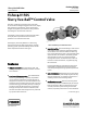


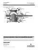

Slurry Vee-Ball Valve
D103154X012
Product Bulletin
51.3:V150S
February 2013
3
Specifications
Valve Sizes
J NPS 3, J 4, J 6, J 8, J 10, and J 12
End Connection
V150S: CL150 Raised-face flange
Face to Face Dimension
Seefigure2
Maximum Inlet Pressure
Consistent with pressure-temperature ratings per
ASME B16.34 but do not exceed the material
temperature capabilities shown below or the pressure
drop limitations
Maximum Shut Off Pressure
See tables 3 and 4
Shutoff Classification
Class I per ANSI/FCI 70-2 and IEC 60534-4
(Class II and better not available). A defined initial
maximum leak rate can be provided subject to review
of service conditions.
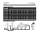
Construction Materials
Standard Construction: See table 1
Temperature Capability
For Trim 1: 427_C(801_F) maximum
For Trims 2 and 3: 230_C(446_F) maximum
For materials: See table 1
Flow Characteristic
Approximately equal percentage
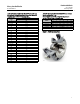
Dimensions
See figures 2 and 3
Flow Direction
Reverse flow recommended (into concave face of
ball, out through the flow ring)
Flow Coefficients
See Fisher Catalog 12
Maximum Ball Rotation
90 degrees
Valve Installation
Shaft axis to be horizontal
Actuator Mounting
Right-hand or left-hand, as viewed from upstream
end of valve
Valve/Actuator Action
With diaphragm or piston rotary actuator and splined
shaft, the valve is field-reversible between PDTC or
PDTO:
J push-down-to-close (extending actuator
rod closes valve) and
J push-down-to-open
(extending actuator rod opens valve)
Actuator Size Selection
Contact your Emerson Process Management sales
office for information
Approximate Weight
NPS 3: 15 kg (33 lb)
NPS 4: 28 kg (62 lb)
NPS 6: 45 kg (99 lb)
NPS 8: 82 kg (180 lb)
NPS 10: 120kg(265lb)
NPS 12: 178kg(390lb)