
Reference Manual

7−9
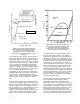
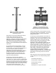
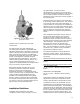
Figure 7-11. The TBX showing external
spraywater manifold.
W8520
provides Class V shutoff and a linear flow
characteristic.
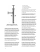
The TBX typically uses high-performance,
pneumatic piston actuators in combination with
FIELDVUE Digital Valve Controllers to achieve full
stroke in less than two seconds while maintaining
highly accurate step response. The FIELDVUE
instruments along with AMS ValveLinkt software
provide a self-diagnostic capability that gives
answers about valve performance. The current
valve/actuator signature (seat load, friction, etc.)
can be compared against previously stored
signatures to identify performance changes before
they cause process control problems.
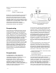
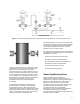
When piping dictates, the TBX valve can be
provided as separate components, allowing
pressure control in the valve body and
temperature reduction in a downstream steam
cooler. The steam cooler is equipped with a water
supply manifold (multiple manifolds are also
possible). The manifold provides cooling water
flow to a number of individual spray nozzles that
are installed in the pipe wall of the cooler section.
The result is a fine spray injected radially into the
high turbulence of the axial steam flow.
Installation Guidelines
Installation of desuperheaters and steam
conditioning valves is key to long term success
and performance. It is best to install
desuperheaters in a straight run of horizontal or
vertical pipe. Installation in elbows is also possible,
but it can affect system turndown and thermal
stratification due to momentum caused changes in
the velocity profile.
Momentum forces the majority of the steam flow
to the outside surfaces of the bend. This results in
a low velocity void on the inside of the elbow. If
high turndowns are not required, this installation is
satisfactory since the voids would rarely be below
minimum velocity at maximum flow. As the flow is
reduced, however, these areas may lose their
ability to perform as required to desuperheat the
steam.
Other installation parameters that are always of
interest to the piping designer are how much
straight run of pipe is required and where the
temperature sensor should be located. Both are
thermally derived questions and require thermally
derived answers. It is desirable to have the
thermal sensor as close as possible to the
desuperheater in order to reduce the signal lag
time. It is also desirable not to have any piping
components (e.g., elbows or tees) that would
detract from the thermal process.
The following equations provide guidelines for
designing a proper system. These equations
relate to time required for complete vaporization
and mixing.
Downstream Straight Pipe Requirements (SPR):
SPR (ft) = 0.1 Sec. x Maximum Steam Velocity
(ft/sec)
Downstream Temperature Sensor Distance (TS):
15% Spraywater or less:
TS (ft) = 0.2 Sec. x Maximum Steam Velocity
(ft/sec)
Greater than 15% Spraywater:
TS (ft) = 0.3 Sec. x Maximum Steam Velocity
(ft/sec)
Temperature control is not limited to receiving a
signal from a downstream temperature sensor.
Another valid alternative is feed-forward control.
Feedforward control is accomplished using an
algorithm that is characterized specifically to the
valve installed in the application. The algorithm is
programmed into the distributed control system to
provide an accurate calculation of the spray water
that is required to reduce the steam enthalpy and
temperature to the desired outlet set point. The
algorithm requires input of upstream temperature