
Reference Manual


6−5
times when this is the area of interest, but the
noise levels on the outside of that pipe are the
prime requirement. This method must account for
the change in the noise as the reference location
moves from inside the pipe to outside the pipe.
The pipe wall has physical characteristics, due to
its material, size, and, shape, that define how well
the noise will transmit through the pipe. The
fluid-borne noise inside the pipe interacts with the
inside pipe wall causing the pipe wall to vibrate,
then the vibration transmits through the pipe wall
to the outside pipe wall, and there the outside pipe
wall interacts with the atmosphere to generate
sound waves. These three steps of noise
transmission are dependent upon the noise
frequency. The method represents the frequency
of the valve noise by determining the peak
frequency of the valve noise spectrum. It also
determines the pipe transmission loss as a
function of frequency. The method then compares
the internal noise spectrum to determine how
much the external sound pressure will be
attenuated by the pipe wall.
5. Account for distance and calculate the sound
pressure level at the observer’s location.
Step four delivers the external sound pressure
level at the outside surface of the pipe wall.
Again, basic acoustic theory is applied to calculate
the sound pressure level at the observer’s
location. Sound power is constant for any given
situation, but the associated sound pressure level
varies with the area of distributed power. As the
observer moves farther away from the pipe wall,
the total area of distributed sound power
increases. This causes the sound pressure level
to decrease.
Methods to Attenuate Noise
With increasing interest in the environmental
impact of all aspects of industry, there are
increasing demands for noise abatement
procedures and equipment.
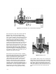
In a closed system, (not vented to the
atmosphere) noise becomes airborne only by
transmission through the valves and adjacent
piping that contains the flowstream. The sound
field in the flowstream forces these solid
boundaries to vibrate, causing disturbances in the
surrounding air to propagate as sound waves.
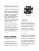
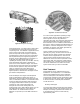
Figure 6-1. Whisper Trim I cage used for reducing
aerodynamic noise
W1257/IL
Noise control techniques fall into one of two basic
categories:
D Source treatment
D Path treatment
While preventing noise at the source is the
preferred approach to noise control, it is
sometimes economically or physically impractical
due to particular application requirements. Path
treatment is then a reasonable approach. There
are also instances when source treatment alone
does not provide sufficient noise reduction; path
treatment is then used as a supplement.
In any event, the decision to use source
treatment, path treatment, or a combination of
both should be made only after the application
requirements and alternative approaches have
been thoroughly analyzed.
Source Treatment
The Fisher Whisper Trimt I cage, illustrated in
figure 6-1 , is interchangeable with standard trim in
many globe valves. It uses many narrow parallel
slots designed to minimize turbulence and provide
a favorable velocity distribution in the expansion
area of the valve. It provides a multitude of low
noise flowpaths, which combine to produce less
overall noise than standard cages. A Whisper Trim
I cage is most efficient when the ratio of pressure
drop to inlet pressure is equal to or less than 0.65
(that is, ΔP/P
1
is less than or equal to 0.65). In
addition, this approach is most effective when the
maximum downstream velocity of the fluid is equal
to or less than half the sonic velocity of that fluid.
This style of cage will provide up to 18 dBA
attenuation versus a standard cage with little
sacrifice in flow capacity.