
Reference Manual


5−5
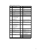
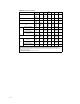
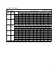
Table 5-1. Abbreviations and Terminology
Symbol Symbol
C
v
Valve sizing coefficient P
1
Upstream absolute static pressure
d Nominal valve size P
2
Downstream absolute static
pressure
D Internal diameter of the piping P
c
Absolute thermodynamic critical
pressure
F
d
Valve style modifier,
dimensionless
P
v
Vapor pressure absolute of liquid at
inlet temperature
F
F
Liquid critical pressure ratio factor,
dimensionless
ΔP Pressure drop (P
1
-P
2
) across the
valve
F
k
Ratio of specific heats factor,
dimensionless
ΔP
max(L)
Maximum allowable liquid sizing
pressure drop
F
L
Rated liquid pressure recovery
factor, dimensionless
ΔP
max(LP)
Maximum allowable sizing pressure
drop with attached fittings
F
LP
Combined liquid pressure recovery
factor and piping geometry factor
of valve with attached fittings
(when there are no attached
fittings, F
LP
equals F
L
),
dimensionless
q Volume rate of flow
F
P
Piping geometry factor,
dimensionless
q
max
Maximum flow rate (choked flow
conditions) at given upstream
conditions
G
f
Liquid specific gravity (ratio of
density of liquid at flowing
temperature to density of water at
60_F), dimensionless
T
1
Absolute upstream temperature
(degree K or degree R)
G
g
Gas specific gravity (ratio of
density of flowing gas to density of
air with both at standard
conditions
(1)
, i.e., ratio of
molecular weight of gas to
molecular weight of air),
dimensionless
w Mass rate of flow
k Ratio of specific heats,
dimensionless
x Ratio of pressure drop to upstream
absolute static pressure (ΔP/P
1
),
dimensionless
K Head loss coefficient of a device,
dimensionless
x
T
Rated pressure drop ratio factor,
dimensionless
M Molecular weight, dimensionless Y Expansion factor (ratio of flow
coefficient for a gas to that for a
liquid at the same Reynolds
number), dimensionless
N Numerical constant
Z Compressibility factor,
dimensionless
γ
1
Specific weight at inlet conditions
υ Kinematic viscosity, centistokes
1. Standard conditions are defined as 60_F (15.5_C) and 14.7 psia (101.3kPa).