
Reference Manual


5−3
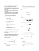
source is a header maintained at 500 psig and
500_F. A 6-inch line from the steam main to the
process is being planned. Also, make the
assumption that if the required valve size is less
than 6 inches, it will be installed using concentric
reducers. Determine the appropriate ED valve with
a linear cage.
1. Specify the necessary variables required to
size the valve.
D Desired valve design—ANSI Class 300 ED
valve with a linear cage. Assume valve size is 4
inches.
D Process fluid—superheated steam
D Service conditions—
w = 125,000 lb/h
P
1
= 500 psig = 514.7 psia
P
2
= 250 psig = 264.7 psia
DP = 250 psi
x = DP/P
1
= 250/514.7 = 0.49
T
1
= 500_F
g1
= 1.0434 lb/ft
3
(from properties of
saturated steam table)
k= 1.28 (from properties of saturated steam
table)
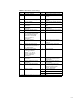
2. Determine the appropriate equation constant,
N, from the equation constants table 3-2 in
chapter three.
Because the specified flow rate is in mass units,
(lb/h), and the specific weight of the steam is also
specified, the only sizing equation that can be
used is that which contains the N
6
constant.
Therefore, N
6
= 63.3
3. Determine F
p
, the piping geometry factor.
F
p
+
ƪ
1 )
SK
N
2
ǒ
C
v
d
2
Ǔ
2
ƫ
*1ń2
where,
N
2
= 890, determined from the equation
constants table
d = 4 in.
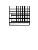
C
v
= 236, which is the value listed in the flow
coefficient table 4-2 for a NPS 4 ED valve at
100% total travel.
and
SK + K
1
) K
2
+ 1.5
ǒ
1 *
d
2
D
2
Ǔ
2
+ 1.5
ǒ
1 *
4
2
6
2
Ǔ
2
+ 0.463
Finally:
F
p
+
ȧ
ȱ
Ȳ
1 )
0.463
890
ǒ
(
1.0
)(
236
)
(
4
)
2
Ǔ
2
ȧ
ȳ
ȴ
*1ń2
+ 0.95
4. Determine Y, the expansion factor.
Y + 1 *
x
3F
k
x
TP
where,
F
k
+
k
1.40
+
1.28
1.40
+ 0.91
x + 0.49(Ascalculatedinstep1.)
Because the size 4 valve is to be installed in a
6-inch line, the x
T
term must be replaced by x
TP
.
x
TP
+
x
T
F
p
2
ƪ
1 )
x
T
K
i
N
5
ǒ
C
v
d
2
Ǔ
2
ƫ
*1
where,
N
5
= 1000, from the equation constants table
d = 4 inches
F
p
= 0.95, determined in step three
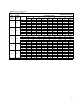
x
T
= 0.688, a value determined from the
appropriate listing in the flow coefficient
table