
Reference Manual


5−2
to produce critical, or maximum, flow through the
valve when F
k
= 1.0
When the control valve to be installed has fittings,
such as reducers or elbows attached to it, their
effect is accounted for in the expansion factor
equation by replacing the x
T
term with a new
factor x
TP
. A procedure for determining the x
TP
factor is described in the following section:
Determining x
TP
, the Pressure Drop Ratio Factor.
Note: Conditions of critical pressure
drop are realized when the value of x
becomes equal to or exceeds the
appropriate value of the product of
either F
k
*x
T
or F
k
*x
TP
at which
point::
y + 1 *
x
3F
k
x
T
+ 1 * 1ń3 + 0. 667
In actual service, pressure drop ratios can, and
often will exceed the indicated critical values. At
this point, critical flow conditions develop. Thus,
for a constant P
1
, decreasing P
2
(i.e., increasing
DP) will not result in an increase in the flow rate
through the valve. Therefore, the values of x
greater than the product of either F
k
*x
T
or F
k
*x
TP
must never be substituted in the expression for Y.
This means that Y can never be less than 0.667.
This same limit on values of x also applies to the
flow equations introduced in the next section.
5. Solve for the required C
V
using the appropriate
equation.
For volumetric flow rate units —
D when specific gravity, G
g
, of the gas has
been specified:
C
v
+
q
N
7
F
p
P
1
Y
x
G
g
T
1
Z
Ǹ
D when molecular weight, M, of the gas has
been specified:
C
v
+
q
N
9
F
p
P
1
Y
x
MT
1
Z
Ǹ
For mass flow rate units —
D when specific weight, g
1
, of the gas has been
specified:
C
v
+
w
N
6
F
p
YxP
1
g
1
Ǹ
D when molecular weight, M, of the gas has
been specified:
C
v
+
M
N
8
F
p
P
1
Y
xM
T
1
Z
Ǹ
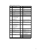
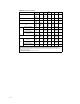
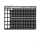
6. Select the valve size using the appropriate flow
coefficient table using the calculated C
V
value.
Determining x
TP
, the Pressure Drop
Ratio Factor
When the control valve is to be installed with
attached fittings such as reducers or elbows, their
affect is accounted for in the expansion factor
equation by replacing the x
T
term with a new
factor, x
TP
.
x
TP
+
x
T
F
p
2
ƪ
1 )
x
T
K
i
N
5
ǒ
C
v
d
2
Ǔ
2
ƫ
*1
where,
N
5
= numerical constant found in the equation
constants table
d = assumed nominal valve size
C
V
= valve sizing coefficient from flow
coefficient table at 100% travel for the assumed
valve size
F
p
= piping geometry factor
x
T
= pressure drop ratio for valves installed
without fittings attached. x
T
values are included
in the flow coefficient tables.
In the above equation, K
i
is the inlet head loss
coefficient, which is defined as:
K
i
+ K
1
) K
B1
where,
K
1
= resistance coefficient of upstream fittings
(see the procedure: Determining F
p
, the Piping
Geometry Factor, which is contained in Chapter
3: Liquid Valve Sizing
K
B1
= Inlet Bernoulli coefficient (see the
procedure: Determining F
p
, the Piping
Geometry Factor, which is contained in chapter
three: Liquid Valve Sizing
Compressible Fluid Sizing Sample
Problem No. 1
Assume steam is to be supplied to a process
designed to operate at 250 psig. The supply