
Reference Manual


www.Fisher.com
Chapter 5
Gas Sizing
This chapter addresses the six-step procedure for
sizing control valves for compressible flow using
the standardized ISA procedure. All six steps are
outlined below, and must be accounted for when
sizing a valve for compressible flow. Steps three
and four are involved in determining specific sizing
factors that may or may not be required in the
sizing equation depending on the service
conditions of the application. When steps three
and/or four are required, refer to the appropriate
section of the book referenced below.
Standardized ISA Procedure
1. Specify the necessary variables required to
size the valve as follows:
D Desired valve design (globe, butterfly, ball)
D Process fluid (air, natural gas, steam, etc.)
D Appropriate service conditions (q, or w, P
1
,
P
2
or DP, T
1
, G
g
, M, k, Z, and g
1
)
The ability to recognize the appropriate terms for a
specific valve sizing application is gained through
experience sizing valves for different applications.
Refer to the notations table in chapter three for
any new or unfamiliar terms.
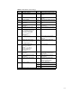
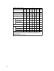
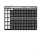
2. Determine the equation constant, N.
N is a numerical constant contained in each of the
flow equations to provide a means for using
different systems of units. Values for these various
constants and their applicable units are given in
the equation constants table 5-2 at the end of this
chapter.
Use N
7
or N
9
when sizing a valve with a specified
flow rate in volumetric units (scfh or m
3
/h).
Selecting the appropriate constant depends upon
the specified service conditions. N
7
is used only
when specific gravity, G
g
, has been specified
along with the other required service conditions.
N
9
is used only when the molecular weight, M, of
the gas has been specified.
Use N
6
or N
8
when sizing a valve with a specified
flow rate in mass units (lb/h or kg/h). In this case,
N
6
is used only when specific weight, g
1
, has been
specified along with the other required service
conditions. N
8
is used only when the molecular
weight, M, of the gas has been specified.
3. Determine F
p
, the piping geometry factor.
F
p
is a correction factor that accounts for any
pressure losses due to piping fittings such as
reducers, elbows, or tees that might be attached
directly to the inlet and outlet connections of the
control valve. If such fittings are attached to the
valve, the F
p
factor must be considered in the
sizing procedure. If no fittings are attached to the
valve, F
p
has a value of one and drops out of the
sizing equation.
For rotary valves with reducers, other valve
designs and fitting styles refer to the determining
piping geometry section of chapter three to
determine the appropriate F
p
value.
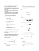
4. Determine Y, the expansion factor.
Y + 1 *
x
3F
k
x
T
where,
F
k
= k/1.4, the ratio of specific heats factor
k = Ratio of specific heats
x = DP/P
1
x
T
= The pressure drop ratio factor for valves
installed without attached fittings. More
definitively, x
T
is the pressure drop ratio required