
Reference Manual


4−13
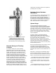
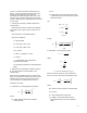
Figure 4-14. Cavitrol IV trim provides cavitation
protection at pressures to 6500 psi. It uses
expanding flow areas to affect a four-stage
pressure drop. All significant pressure drop is
taken downstream of the shutoff seating surface.
W3668−1
Separate Seating and Throttling
Locations
In a modern power plant, most cavitating
applications require a control valve to not only
provide cavitation control, but also provide tight
shutoff. The best way to accomplish this is to
separate the throttling location from the seating
location as shown in figure 4-14. The seating
surface of the plug is upstream of the throttling
location, and the upper cage is designed such that
it takes very little pressure drop. The seating
surface experiences relatively low flow velocities
as velocity is inversely related to pressure. A
recent technological advancement has been to
implement the use of a softer seating material
relative to the material of the plug. This allows for
a slight deformation of the seating material, which
provides much better plug/seat contact and, as a
result, greatly enhanced shutoff capability. Valves
utilizing this soft seating material are capable of
providing Class VI shutoff.
Cavitation Control Hardware
Alternatives
In the previous sections, theories behind modern
types of cavitation control hardware were
discussed. This section presents alternatives to
the, sometimes, costly cavitation hardware.
Guidelines are also presented to help determine
when cavitation control hardware is required or
when other alternatives can be employed.
System Design
Correct liquid system design is the most
economical way to prevent the damaging effects
caused by cavitation without applying cavitation
prevention control valves. Unfortunately, even the
best system design is likely to need cavitation type
control valves, but by applying certain design
features, the complexity of these control valves
may be simplified.
The most common and oldest method of
designing a liquid flow system where large
pressure drops must occur is to use a standard
trim control valve with a downstream
backpressure device. Although these devices
come in various sizes, shapes, and designs, they
all perform the same function of lowering the
pressure drop across the control valve by raising
its downstream pressure.
Because the downstream pressure of the valve is
increased, the vena contracta pressure is
increased. If the backpressure device is sized
correctly, the vena contract pressure will not fall
below the vapor pressure, and cavitation will not
occur.
While this is a simple and cost-effective way to
prevent cavitation damage in the control valve,
there are several serious considerations to look at
before using a downstream backpressure device.
D A larger valve may be required to pass the
required flow as the pressure drop is lowered.
D Although cavitation may not occur at the
control valve, it may occur at the backpressure
device.
D The backpressure device can only be sized
for one condition. If other conditions exist, the