
Reference Manual


4−12
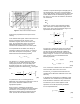
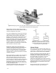
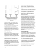
Figure 4-13. By combining the geometric effects of
thick plates and thin plates, it is possible to design
a flow passage that optimizes capacity and
recovery coefficient values. These carefully
designed passages are used exclusively in
Cavitrol cages.
E0113−1
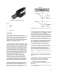
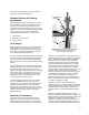
In the last restriction, where cavitation is most
likely to occur, the pressure drop is only a small
percentage of the total drop, and the pressure
recovery is substantially lowered.
The expanding flow area concept requires fewer
pressure drop stages to provide the same
cavitation protection as the equal area concept.
Because the pressure drop of the last stage is
rather low compared to the total pressure drop, if
cavitation does occur, the intensity and cavitation
damage will be much less.
Drilled Hole Design
Drilled hole cages are used in the Fisher Cavitrolt
cavitation control trim line to provide a tortuous
path, pressure drop staging, and expanding flow
area. The design of each particular drilled hole has
a significant impact on the overall pressure
recovery of the valve design.
Figure 4-13 illustrates a cross section of three
types of drilled holes that could be used in a
cavitation control cage. The thin plate design is an
inefficient flow device, but it does provide a high
F
L
2
and, therefore, a low pressure recovery. The
thick plate design provides an efficient design, but
also provides a high pressure recovery as denoted
by a low F
L
2
value.
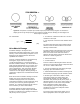
The Cavitrol trim hole design is a balance between
the thick plate and the thin plate hole designs. It
provides relatively high flow efficiency while
maintaining a high F
L
2
, which results in a low
pressure recovery. This design represents the
optimal choice between capacity and cavitation
control.
Another benefit of this type of drilled hole design is
that the vena contracta point is further from the
exit of the hole when compared to a straight
through drilled hole. Consequently, if pressure
recovery above the vapor pressure occurs
(cavitation), it will do so further away from the
external wall of the cage, and the amount of
damage will be smaller.
One disadvantage of cavitation control trims is the
potential for flow passages to become plugged
with sand, dirt or other debris. Particulate laden
flow is common to water injection applications.
The flowing media often times contains small
particulate that can plug the passages, restricting
or totally stopping flow through the valve. If this
potential exists, the particles must be removed
from the flow stream, usually by filtration or an
alternative approach to cavitation should be taken.
An alternative is to use a trim that is designed to
allow the particulate to pass, but still control
cavitation. The Fisher Dirty Service Trim (DST)
has been designed to allow particles up to 3/4” to
be passed and to control cavitation up to pressure
drops of 4000 psi. This trim has been used
extensively in produced water injection, water
injection pump recirculation, and other liquid flow,
particulate containing, high pressure drop
applications.
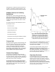
Characterized Cage
The characterized cage design theory has evolved
from the fact that “capacity is inversely related to a
design’s ability to prevent cavitation.” In those
applications where the pressure drop decreases
as the flow rate increases, characterized cages
can be used to optimize cavitation prevention and
capacity.
For a Cavitrol III trim design, as the travel
increases, the cage design changes. It begins as
a pressure-staging design and then develops into
a straight-through hole design. Consequently, the
cavitation control ability of this trim design is
greatest at low travels and decreases with
increasing valve plug travel.
Care should be taken to employ characterized
cages only in applications where the pressure
drop decreases as travel increases.