
Reference Manual


4−11
impingement on a material surface will not occur
as there is essentially no material surface. This
system design will help prevent flashing damage.
Hardware Choices for Cavitating
Applications
The design of a control valve greatly affects the
ability of a valve to control cavitation. This section
discusses the theories behind each type of trim
design that is used for cavitation control and also
reviews each type of Fisher trim used to control
cavitation.
The design theories or ideas behind the various
trim designs include:
D Tortuous path
D Pressure drop staging
D Expanding flow area
D Drilled hole design
D Characterized cage
D Separation of seating and throttling locations
D Cavitation control in lieu of prevention
Tortuous Path
Providing a tortuous path for the fluid through the
trim is one way to lower the amount of pressure
recovery of that trim. Although this tortuous path
can be in the form of drilled holes, axial flow
passages or radial flow passages, the effect of
each design is essentially the same. The use of a
tortuous path design concept is used in virtually
every cavitation control style of hardware.
Pressure Drop Staging
This approach to damage control routes flow
through several restrictions in series, as opposed
to a single restriction. Each restriction dissipates a
certain amount of available energy and presents a
lower inlet pressure to the next stage.
A well-designed pressure-staging device will be
able to take a large pressure differential while
maintaining the vena contracta pressure above the
vapor pressure of the liquid, which prevents the
liquid from cavitating.
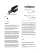
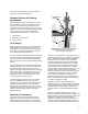
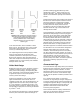
Figure 4-12. In Cavitrol trim, the pressure drop is
staged in two or more unequal steps. Staging is
accomplished by increasing the flow area from
stage to stage. This stepped reduction allows full
pressure drop without the vena contracta pressure
falling below the vapor pressure of the liquid.
A2149-1
For the same pressure differential then, the vena
contracta pressure in conventional trim will be
lower than for the staged trim, and the liquid will
be more prone to cavitate.
Trims that dissipate available energy have an
additional advantage. If the design pressure
differential is exceeded and cavitation does occur,
the intensity will be less. This is because the
pressure that causes the collapse of cavities (i.e.,
the recovered pressure) will be less.
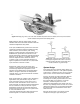
Expanding Flow Areas
The expanding flow area concept of damage
control is closely related to the pressure drop
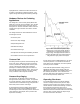
staging concept. Figure 4-12 shows a pressure
versus distance curve for flow through a series of
fixed restrictions where the area of each
succeeding restriction is larger than the previous.
Notice that the first restriction takes the bulk of the
pressure drop, and the pressure drop through
successive sections decreases.