
Reference Manual


4−10
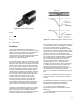
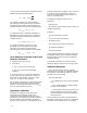
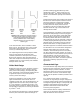
Figure 4-10. Rotary plug valves, such as the V500 Vee-Ball valve(reverse flow trim direction, trim level 3) have excellent
erosion resistance and perform well in flashing service
W8359
better resistance than the carbon steels, and the
stainless steels have even better resistance than the
chromium-molybdenum alloy steels.
In the past, ASME SA217 grade C5 was the most
commonly specified chromium-molybdenum alloy
steel. However, because of the poor casting,
welding, and manufacturing characteristics of C5,
ASME SA217 grade WC9 has become a more
popular alternative. Experience indicates that WC9
performs on par with C5 in cavitation and flashing
services despite its lower chromium content
(2-1/4% vs. 5%). This is apparently because its
higher molybdenum content (1% vs. 1/2%) makes
up for the lower chromium content.
ASTM A217 grade C12A is becoming more
common in the power industry. This material has
excellent high temperature properties, and is
typically used at temperatures exceeding 1000°F
(538°C). Its higher chromium and molybdenum
contents (9% Cr, 1% Mo) would indicate excellent
cavitation resistance.
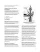
While angle bodies are a better choice for flashing
applications than globe bodies, they are also a
more economical choice in most cases. This is
because carbon steel bodies can be used in an
angle valve with an optional hardened downstream
liner (17-4PH SST or alloy 6) because only the
downstream portion of the valve will experience
the flashing liquid (see figure 4-9). If a globe valve
is used, it is better to use a
chromium-molybdenum alloy steel body because
the flashing will occur within the body itself.
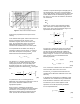
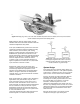
Figure 4-11. Location of a control valve can often
be changed to lengthen its life or allow use of less
expensive products. Mounting a heater drain valve
near the condenser is a good example.
E0864
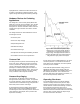
System Design
This section discusses system design where it is
assumed flashing will occur. The optimum position
of the valve in a flashing service can have a great
impact on the success of that valve installation.
Figure 4-11 shows the same application with the
exception of the location of the control valve.
These figures are fairly representative of a valve
that controls flow to a condenser. In the top
illustration, the flashing will occur in the
downstream pipe between the control valve and
the tank. Any damage that occurs will do so in that
downstream piping area. In the bottom illustration,
the flashing will occur downstream of the valve
within the tank.
Because the tank has a much larger volume
compared to the pipe, high velocity fluid