
Reference Manual


4−9
recent experience should be used to select the
best valve for specific applications.
Hardware Choices for Flashing
Applications
It was stated previously that flashing is a liquid
flow phenomenon that is defined by the system,
and not by the valve design. Therefore, since
flashing cannot be prevented by the control valve,
all that can be done is to prevent flashing damage.
There are three main factors that affect the
amount of flashing damage in a control valve:
1. Valve design
2. Materials of construction
3. System design
Valve Design
While valve design has no bearing upon whether
flashing does or does not occur, it can have a
large impact on the intensity of flashing damage.
Generally, there are two valve designs that are
more resistant to flashing damage.
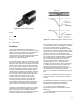
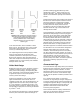
An angle valve with standard trim in the flow down
direction and with a downstream liner is perhaps
the best solution to preventing flashing damage.
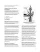
figure 4-9 shows a typical angle valve for flashing
service.
This construction is an excellent choice because
flashing damage occurs when high velocity vapor
bubbles impinge on the surface of a valve. An
angle valve reduces the impingement by directing
flow into the center of the downstream pipe, not
into the valve body. If damage does occur, the
downstream liner can be replaced much more
economically than the valve body.
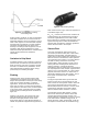
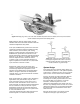
A rotary plug style of valve is also an excellent
choice for medium to low pressure flashing
applications. This valve can be installed with the
plug facing the downstream side of the body
(figure 4-10) so when flashing occurs, it does so
downstream of the valve. In some cases, a spool
piece of sacrificial pipe is used to absorb the
flashing damage.
Materials of Construction
There are several factors that determine the
performance of a given material in a particular
flashing and/or cavitating situation including the
materials’ toughness, hardness, and its corrosion
Figure 4-9. Fisher EAS valve with outlet liner is
used for flashing service. The liner resists
erosion and protects the body.
W0970
RESTRICTED-TRIM
ADAPTOR
LINER
resistance in the application environment. Within a
given material family (e.g. the 400-series stainless
steels), hardness is a fairly accurate method for
ranking materials. However, when comparing
materials from different families, hardness does
not correlate with overall resistance to damage.
For example, cobalt-chromium-tungsten based
alloy 6 has much more resistance to cavitation
and flashing than either hardened type 410 or 17-4
stainless steels, even though they all exhibit
roughly the same hardness. In fact, alloy 6 equals
or exceeds the performance of many materials
with a hardness of 60 HRC and higher. The
superior performance of alloy 6 is attributed to a
built-in “energy-absorbing” mechanism shared by
a number of cobalt-base alloys.
Materials commonly used for flashing and
cavitating services are alloy 6 (solid and overlays),
nickel-chromium-boron alloys (solid and overlays),
hardened 440C stainless steel, hardened 17-4
stainless steel, and hardened 410/416 stainless
steel.
Because the standard materials used in valve
bodies are relatively soft, selection for cavitation and
flashing resistance must rely upon factors other than
hardness. In general, as the chromium and
molybdenum contents increase, the resistance to
damage by both cavitation and flashing increase.
Thus, the chromium-molybdenum alloy steels have