
Reference Manual

4−7
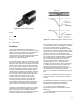
dominant. Analytical estimations of vapor bubble
collapse pressures do not suggest that the shock
waves are on a damaging order of magnitude —
at least during the initial collapse. Experimental
studies bear this out. They also reveal that
resulting collapse pressures increase in magnitude
with subsequent rebound collapses and become
potentially damaging.
The other primary component of attack, chemical
attack, is perhaps more significant because it
interacts with the mechanical component rather
than acting by itself. After a period of mechanical
attack, many of the protective coatings of a
material (films, oxides, etc.) are physically
removed, making the base material more
vulnerable to chemical attack.
Just as a number of variables have an affect on
the behavior of individual cavities, a number of
variables influence the degree and extent of
material damage. The principal variables that
influence cavitation damage include air content,
pressure, velocity and temperature.
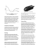
Air content impacts cavitation damage primarily
through its effect on cavity mechanics. Again, two
opposing trends are evident on increasing the
amount of air. Adding air supplies more entrained
air nuclei which, in turn, produce more cavities
that can increase the total damage. After a point,
however, continued increases in air content
disrupt the mechanical attack component and
effectively reduce the total damage.
Pressure effects also exhibit two opposing trends.
Given a fixed inlet pressure P
1
, decreasing the
backpressure P
2
tends to increase the number of
cavities formed, which creates a worse situation.
However, a lower backpressure also creates a
lower collapse pressure differential (P
2
− P
v
),
resulting in a decrease in the intensity of the
cavitation.
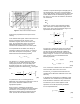
An additional pressure effect, unrelated to the
above, concerns the location of damage. As the
backpressure is changed, the pressure required to
collapse the cavities moves upstream or
downstream depending upon whether the
pressure is increased or decreased, respectively.
In addition to a change in the severity of the total
damage, there may be an accompanying change
in the physical location of the damage when
pressure conditions are altered.
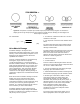
It should now be apparent that the cavitation and
flashing damage process is a complex function of:
1. Intensity and degree of cavitation (cavitation
attack)
2. Material of construction (material response)
3. Time of exposure
While the above-mentioned influences have been
observed, they remain to be quantified. Often,
experience is the best teacher when it comes to
trying to quantify cavitation damage.
Noise
Although the noise associated with a cavitating
liquid can be quite high, it is usually of secondary
concern when compared to the material damage
that can exist. Therefore, high intensity cavitation
should be prevented to decrease the chance of
material damage. If cavitation is prevented, the
noise associated with the liquid flow will be less
than 90 dBA.
For a flashing liquid, studies and experience have
shown that the noise level associated with the
valve will be less than 85 dBA, regardless of the
pressure drop involved to create the flashing.
Cavitation / Flashing Damage
Coefficients and Product Selection
Cavitation in control valves can be an application
challenge. It is important to understand the
guidelines when selecting an appropriate valve
and trim. Experience, knowledge of where
cavitation problems begin, and the effect of valve
size and type, are all useful in deciding which
valve and trim can be used.
Terminology
F
L
: Pressure recovery coefficient. A valve
parameter used to predict choked flow.
ΔP
max
: Allowable sizing pressure drop. The
limiting pressure drop beyond which any increase
in pressure drop brought about by decreasing P
2
will not generate additional flow through the valve.
Therefore the valve is “choked”. Per equation 28
of chapter 3:
DP
max(L)
+ F
L
2
(P
1
* F
F
P
v
)
where,
P
1
= Upstream absolute static pressure
P
v
= Absolute vapor pressure at inlet temperature