
Reference Manual


4−5
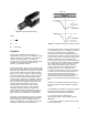
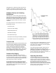
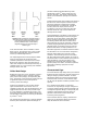
Figure 4-7. Viscous Flow Correction Factors
A3446
losses were proportional to the square of the
velocity.
In the laminar flow regime, these same losses are
linearly proportional to the velocity; in the
transitional regime, these losses tend to vary.
Thus, for equivalent flow rates, the pressure
differential through a conduit or across a
restriction will be different for each flow regime.
To compensate for this effect (the change in
resistance to flow) in sizing valves, a correction
factor was developed. The required C
v
can be
determined from the following equation:
C
v
reqȀd
+ F
R
C
v
rated
(37)
The factor F
R
is a function of the Reynolds
number and can be determined from a simple
nomograph procedure, or by calculating the
Reynolds number for a control valve from the
following equation and determining F
R
from figure
4-7.
Re
v
+
N
4
F
d
Q
nF
L
1ń2C
v
1ń2
ƪ
1
N
2
(F
L
)
2
ǒ
C
v
d
2
Ǔ
2
) 1
ƫ
1ń4
(38)
To predict flow rate, or resulting pressure
differential, the required flow coefficient is used in
place of the rated flow coefficient in the
appropriate equation.
When a valve is installed in a field piping
configuration which is different than the specified
test section, it is necessary to account for the
effect of the altered piping on flow through the
valve. (Recall that the standard test section
consists of a prescribed length of straight pipe up
and downstream of the valve.) Field installation
may require elbows, reducers, and tees, which will
induce additional losses immediately adjacent to
the valve. To correct for this situation, two factors
are introduced:
D F
p
D F
lp
Factor F
p
is used to correct the flow equation
when used in the incompressible range, while
factor F
lp
is used in the choked flow range. The
expressions for these factors are:
F
p
+
ƪ
SK
N
2
ǒ
C
v
d
2
Ǔ
2
) 1
ƫ
*1ń2
(39)
F
Ip
+ F
L
ƪ
F
L
2
K
I
N
2
ǒ
C
v
d
2
Ǔ
2
) 1
ƫ
*1ń2
(40)
The term K in equation 39 is the sum of all loss
coefficients of all devices attached to the valve
and the inlet and outlet Bernoulli coefficients.
Bernoulli coefficients account for changes in the
kinetic energy as a result of a cross-sectional flow
area change. They are calculated from the
following equations.
K
B
inlet
+ 1 * (dńD)
4
(41a)
K
B
outlet
+ (dńD)
4
* 1
(41b)
Thus, if reducers of identical size are used at the
inlet and outlet, these terms cancel out.
The term “K
I
” in equation 40 includes the loss
coefficients and Bernoulli coefficient on the inlet
side only.
In the absence of test data or knowledge of loss
coefficients, loss coefficients may be estimated
from information contained in other resources.
The factors F
p
and F
I
would appear in flow
equations 31 and 36 respectively as follows:
For incompressible flow:
Q + F
p
C
v
P
1
* P
2
G
Ǹ
(42)