
Reference Manual


4−4
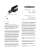
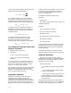
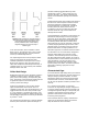
Figure 4-5. Pressure Profiles for Flashing
and Cavitating Flows
A3445
If both of these conditions are met, the possibility
exists that cavitation will occur. Because of the
potentially damaging nature of cavitation, sizing a
valve in this region is not recommended. Special
purpose trims and products to control cavitation
should be considered. Because of the great
diversity in the design of this equipment, it is not
possible to offer general guidelines for sizing
valves with those specialized trims. Please refer to
specific product literature for additional
information.
Cavitation in Pulp Stock
Cavitation behavior in low consistency pulp stock
(less than 4%) is treated as equivalent to that of
water. Generally, pulp stock consistency greater
than 4% is not known to be problematic, as the
stock itself absorbs the majority of the energy
produced by the cavitating microjets.
Flashing
Flashing shares some common features with
choked flow and cavitation in that the process
begins with vaporization of the liquid in the vicinity
of the vena contracta. However, in flashing
applications, the pressure downstream of this
point never recovers to a value that exceeds the
vapor pressure of the fluid. Thus, the fluid remains
in the vapor phase. Schematic pressure profiles
for flashing and cavitating flow are contrasted in
figure 4-5.
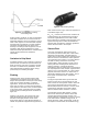
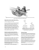
Flashing is of concern not only because of its
ability to limit flow through the valve, but also
because of the highly erosive nature of the
liquid-vapor mixture. Typical flashing damage is
smooth and polished in appearance (figure 4-6) in
Figure 4-6. Typical Flashing Damage
W2842
stark contrast to the rough, cinder-like appearance
of cavitation (figure 4-3).
If P
2
< P
v
, or there are other service conditions to
indicate flashing, the standard sizing procedure
should be augmented with a check for choked
flow. Furthermore, suitability of the particular valve
style for flashing service should be established
with the valve manufacturer. Selection guidelines
will be discussed later in the chapter.
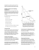
Viscous Flow
One of the assumptions implicit in the sizing
procedures presented to this point is that of fully
developed, turbulent flow. Turbulent flow and
laminar flow are flow regimes that characterize the
behavior of flow. In laminar flow, all fluid particles
move parallel to one another in an orderly fashion
and with no mixing of the fluid. Conversely,
turbulent flow is highly random in terms of local
velocity direction and magnitude. While there is
certainly net flow in a particular direction,
instantaneous velocity components in all directions
are superimposed on this net flow. Significant fluid
mixing occurs in turbulent flow. As is true of many
physical phenomena, there is no distinct line of
demarcation between these two regimes. Thus, a
third regime of transition flow is sometimes
recognized.
The physical quantities which govern this flow
regime are the viscous and inertial forces; this
ratio is known as the Reynolds number. When the
viscous forces dominate (a Reynolds number
below 2,000) the flow is laminar, or viscous. If the
inertial forces dominate (a Reynolds number
above 3,000) the flow is turbulent, or inviscid.
Consideration of these flow regimes is critical
because the macroscopic behavior of the flow
changes when the flow regime changes. The
primary behavior characteristic of concern in sizing
is the nature of the available energy losses. In
earlier discussion it was asserted that, under the
assumption of inviscid flow, the available energy