
Reference Manual


4−2
While the exact mechanisms of liquid choking are
not fully confirmed, there are parallels between
this and critical flow in gas applications. In gas
flows, the flow becomes critical (choked) when the
fluid velocity is equal to the acoustic wave speed
at that point in the fluid. Pure incompressible fluids
have high wave speeds and, practically speaking,
they do not choke. Liquid-to-gas or liquid-to-vapor
mixtures, however, typically have low acoustic
wave speeds (actually lower than that for a pure
gas or vapor), so it is possible for the mixture
velocity to equal the sonic velocity and choke the
flow.
Another way of viewing this phenomenon is to
consider the density of the mixture at the vena
contracta. As the pressure decreases, so does the
density of the vapor phase, hence, the density of
the mixture decreases. Eventually, this decrease
in density of the fluid offsets any increase in the
velocity of the mixture to the point where no
additional mass flow is realized.
It is necessary to account for the occurrence of
choked flow during the sizing process so that
undersizing of a valve does not occur. In other
words, knowing the maximum flow rate a valve
can handle under a given set of conditions is
necessary. To this end, a procedure was
developed which combines the control valve
pressure recovery characteristics with the
thermodynamic properties of the fluid to predict
the maximum usable pressure differential, i.e. the
pressure differential at which the flow chokes.
A pressure recovery coefficient can be defined as:
K
m
+
P
1
* P
2
P
1
* P
vc
(32)
Under choked flow conditions, it is established
that:
P
vc
+ r
c
P
v
(33)
The vapor pressure, P
v
, is determined at inlet
temperature because the temperature of the liquid
does not change appreciably between the inlet
and the vena contracta. The term “r
c
” is known as
the critical pressure ratio, and is another
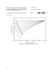
thermodynamic property of the fluid. While it is
actually a function of each fluid and the prevailing
conditions, it has been established that data for a
variety of fluids can be generalized, according to
figure 4-2 or the following equation, without
significantly compromising overall accuracy:
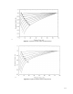
Figure 4-2. Generalized r
c
Curve
A3443 / IL
r
c
+ F
F
+ 0.96 * 0.28
P
vc
P
c
Ǹ
(34)
The value of K
m
is determined individually by test
for each valve style and accounts for the pressure
recovery characteristics of the valve.
By rearranging equation sixteen, the pressure
differential at which the flow chokes can be
determined is known as the allowable pressure
differential:
(P
1
* P
2
)
allowable
+ K
m
(P
1
* r
c
P
v
)
(35)
When this allowable pressure differential is used in
the equation below (equation 14 from chapter 3),
the choked flow rate for the given valve will result.
Q + C
v
P
1
* P
2
G
Ǹ
If this flow rate is less than the required service
flow rate, the valve is undersized. It is then
necessary to select a larger valve, and repeat the
calculations using the new values for C
v
and K
m
.
The equations supplied in the sizing standard are,
in essence, the same as those presented in this
chapter, except the nomenclature has been
changed. In this case:
Q
max
+ N
1
F
L
C
v
P
1
* F
F
P
v
G
Ǹ
(36)