
Reference Manual


3−10
anticipated requirements. The line size is 8-inches,
and an ANSI Class 300 globe valve with an equal
percentage cage has been specified. Standard
concentric reducers will be used to install the valve
into the line. Determine the appropriate valve size.
1. Specify the necessary variables required to
size the valve:
D Desired valve design is an ANSI Class 300
globe valve with equal percentage cage and an
assumed valve NPS 3.
D Process fluid is liquid propane
D Service conditions are q = 800 gpm
P
1
= 300 psig = 314.7 psia
P
2
= 275 psig = 289.7 psia
ΔP = 25 psi
T
1
= 70°F
G
f
= 0.50
P
v
= 124.3 psia
P
c
= 616.3 psia
2. Use an N
1
value of 1.0 from the Equation
Constants table.
3. Determine F
p
, the piping geometry factor.
Because it is proposed to install a NPS 3 valve in
an 8-inch line, it will be necessary to determine the
piping geometry factor, F
p
, which corrects for
losses caused by fittings attached to the valve.
From Equation 19,
Fp +
ƪ
1 )
SK
N
2
ǒ
C
v
d
2
Ǔ
2
ƫ
*1ń2
where,
N
2
= 890, from the Equation Constants Table
d = 3 inches, from step one
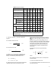
C
v
= 121, from the flow coefficient table for an
ANSI Class 300, NPS 3 globe valve with equal
percentage cage.
To compute ΣK for a valve installed between
identical concentric reducers:
SK + K
1
) K
2
+ 1.5
ǒ
1 *
d
2
D
2
Ǔ
2
+ 1.5
ǒ
1 *
(3)
2
(8)
2
Ǔ
2
+ 1.11
where,
D = 8 inches, the internal diameter of the piping
so,
F
p
+
ƪ
1 )
1.11
890
ǒ
121
3
2
Ǔ
2
ƫ
*1ń2
+ 0.90
4. Determine ΔP
max
(the allowable sizing
pressure drop)
Based upon the small required pressure drop, the
flow will not be choked (ΔP
max
> ΔP).
5. Solve for C
v
, using equation 17.
C
v
+
q
N
1
F
P
P
1
*P
2
Ǹ
G
f
+
800
(
1.0
)(
0.90
)
25
0.5
Ǹ
+ 125.7
6. Select the valve size using the flow coefficient
table and the calculated C
v
value.
The required C
v
of 125.7 exceeds the capacity of
the assumed valve, which has a C
v
of 121.
Although, for this example, it may be obvious that
the next larger size (NPS 4) would be the correct
valve size, this may not always be true, and a
repeat of the above procedure should be carried
out. This is assuming that a NPS 4 valve, C
v
=
203. This value was determined from the flow
coefficient table for an ANSI Class 300, NPS 4
globe valve with an equal percentage cage.
Recalculate the required C
v
using an assumed C
v
value of 203 in the F
p
calculation.