
Reference Manual


3−8
In the above equation, the “K” term is the
algebraic sum of the velocity head loss
coefficients of all of the fittings that are attached to
the control valve.
SK + K
1
) K
2
) K
B1
* K
B2
(20)
where,
K
1
= Resistance coefficient of upstream fittings
K
2
= Resistance coefficient of downstream fittings
K
B1
= Inlet Bernoulli coefficient
K
B2
= Outlet Bernoulli coefficient
The Bernoulli coefficients, K
B1
and K
B2
, are used
only when the diameter of the piping approaching
the valve is different from the diameter of the
piping leaving the valve, whereby:
K
B1
orK
B2
+ 1 *
ǒ
d
D
Ǔ
4
(21)
where,
d = Nominal valve size
D = Internal diameter of piping
If the inlet and outlet piping are of equal size, then
the Bernoulli coefficients are also equal, K
B1
=
K
B2
, and therefore they are dropped from the
equation.
The most commonly utilized fitting in control valve
installations is the short-length concentric reducer.
The equations for this fitting are as follows:
For an inlet reducer:
K
1
+ 0.5
ǒ
1 *
d
2
D
2
Ǔ
2
(22)
For an outlet reducer:
K
2
+ 1.0
ǒ
1 *
d
2
D
2
Ǔ
2
(23)
For a valve installed between identical reducers:
K
1
) K
2
+ 1.5
ǒ
1 *
d
2
D
2
Ǔ
2
(24)
Determining Maximum Flow Rate
(q
max
)
Determine either q
max
or ΔP
max
if it is possible for
choked flow to develop within the control valve
that is to be sized. The values can be determined
by using the following procedures:
q
max
+ N
1
F
L
C
v
P
1
* F
F
P
v
G
f
Ǹ
(25)
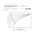
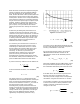
Values for F
F
, the liquid critical pressure ratio
factor, can be obtained from figure 3-3, or from the
following equation:
F
F
+ 0.96 * 0.28
P
v
P
c
Ǹ
(26)
Values of F
L
, the recovery factor for rotary valves
installed without fittings attached, can be found in
published coefficient tables. If the given valve is to
be installed with fittings such as reducer attached
to it, F
L
in the equation must be replaced by the
quotient F
LP
/F
p
, where:
F
LP
+
ƪ
K
1
N
2
ǒ
C
v
d
2
Ǔ
2
)
1
F
L
2
ƫ
*1ń2
(27)
and
K
1
= K
1
+ K
B1
where,
K
1
= Resistance coefficient of upstream fittings
K
B1
= Inlet Bernoulli coefficient
Note: See the procedure for determining F
p
, the
piping geometry factor, for definitions of the other
constants and coefficients used in the above
equations.)
Determining Allowable Sizing Pressure
Drop (DP
max
)
ΔP
max
(the allowable sizing pressure drop) can be
determined from the following relationships:
For valves installed without fittings:
DP
max(L)
+ F
L
2
ǒ
P
1
* F
F
P
v
Ǔ
(28)