
Reference Manual


3−7
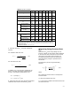
Table 3-2. Equation Constants
(1)
N w q p
(2)
g
T d, D
N
1
0.0865
0.865
1.00
- - -
- - -
- - -
m
3
/h
m
3
/h
gpm
kPa
bar
psia
- - -
- - -
- - -
- - -
- - -
- - -
- - -
- - -
- - -
N
2
0.00214
890
- - -
- - -
- - -
- - -
- - -
- - -
- - -
- - -
- - -
- - -
mm
inch
N
5
0.00241
1000
- - -
- - -
- - -
- - -
- - -
- - -
- - -
- - -
- - -
- - -
mm
inch
N
6
2.73
27.3
63.3
kg/h
kg/h
lb/h
- - -
- - -
- - -
kPa
bar
psia
kg/m
3
kg/m
3
lb/ft
3
- - -
- - -
- - -
- - -
- - -
- - -
N
7
(3)
Normal Conditions
T
N
= 0_C
3.94
394
- - -
- - -
m
3
/h
m
3
/h
kPa
bar
- - -
- - -
deg K
deg K
- - -
- - -
Standard Conditions
T
s
= 15.5_C
4.17
417
- - -
- - -
m
3
/h
m
3
/h
kPa
bar
- - -
- - -
deg K
deg K
- - -
- - -
Standard Conditions
T
s
= 60_F
1360 - - - scfh psia - - - deg R - - -
N
8
0.948
94.8
19.3
kg/h
kg/h
lb/h
- - -
- - -
- - -
kPa
bar
psia
- - -
- - -
- - -
deg K
deg K
deg R
- - -
- - -
- - -
N
9
(3)
Normal Conditions
T
N
= 0_C
21.2
2120
- - -
- - -
m
3
/h
m
3
/h
kPa
bar
- - -
- - -
deg K
deg K
- - -
- - -
Standard Conditions
Ts = 15.5_C
22.4
2240
- - -
- - -
m
3
/h
m
3
/h
kPa
bar
- - -
- - -
deg K
deg K
- - -
- - -
Standard Conditions
T
S
= 60_F
7320 - - - scfh psia - - - deg R - - -
1. Many of the equations used in these sizing procedures contain a numerical constant, N, along with a numerical
subscript. These numerical constants provide a means for using different units in the equations. Values for the
various constants and the applicable units are given in the above table. For example, if the flow rate is given in U.S.
gpm and the pressures are psia, N
1
has a value of 1.00. If the flow rate is m
3
/hr and the pressures are kPa, the N
1
constant becomes 0.0865.
2. All pressures are absolute.
3. Pressure base is 101.3 kPa (1.013 bar)(14.7 psia).
5. Solve for required C
v
, using the appropriate
equation.
For volumetric flow rate units:
C
v
+
q
N
1
F
P
P
1
*P
2
G
f
Ǹ
(17)
For mass flow rate units:
C
v
+
w
N
6
F
P
(P
1
* P
2
)g
Ǹ
(18)
In addition to C
v
, two other flow coefficients, K
v
and A
v
, are used, particularly outside of North
America. The following relationships exist:
K
V
+ (0.865)(C
V
)
A
V
+ (2.40 10
*5
)(C
V
)
6. Select the valve size using the appropriate flow
coefficient table and the calculated C
v
value.
Determining Piping Geometry Factor
(F
p
)
Determine an F
p
factor if any fittings such as
reducers, elbows, or tees will be directly attached
to the inlet and outlet connections of the control
valve that is to be sized. When possible, it is
recommended that F
p
factors be determined
experimentally by using the specified valve in
actual tests.
Calculate the F
p
factor using the following
equation:
F
p
+
ƪ
1 )
SK
N
2
ǒ
C
v
d
2
Ǔ
2
ƫ
*1ń2
(19)
where,
N
2
= Numerical constant found in the Equation
Constants table
d = Assumed nominal valve size
C
v
= Valve sizing coefficient at 100% travel for the
assumed valve size