
Reference Manual
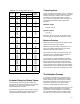


* The ability to recognize which terms are appropriate for a specific sizing
procedure can only be acquired through experience with different valve sizing
problems. If any of the above terms appears to be new or unfamiliar, refer to
the Abbreviations and Terminology Table (table 3-1) for a complete definition.
3−5
Many applications fall outside the bounds of the
basic liquid flow applications just considered.
Rather than develop special flow equations for all
of the possible deviations, it is possible (and
preferred) to account for different behavior with
the use of simple correction factors. These
factors, when incorporated, change the form of
equation 14 to the following:
Q + (N
1
F
P
F
R
)C
V
P
1
* P
2
G
Ǹ
(16)
All of the additional factors in this equation are
explained in the following sections.
Sizing Valves for Liquids
Following is a step-by-step procedure for the
sizing of control valves for liquid flow using the
IEC procedure. Each of these steps is important
and must be considered during any valve sizing
procedure. Steps three and four concern the
determination of certain sizing factors that may, or
may not, be required in the sizing equation
depending upon the service conditions of the
sizing problem. If one, two, or all three of these
sizing factors are to be included in the equation for
a particular sizing problem, please refer to the
appropriate factor determination section(s) located
in the text proceeding step six.
1. Specify the variables required to size the valve
as follows:
D Desired design
D Process fluid (water, oil, etc.)
D Appropriate service conditions Q or w, P
1
, P
2
or ΔP, T
1
, G
f
, P
v
, P
c
, and υ*
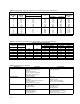
2. Determine the equation constant, N.
N is a numerical constant contained in each of the
flow equations to provide a means for using
different systems of units. Values for these various
constants and their applicable units are given in
the Equation Constants Table (table 3-2).
Use N
1
if sizing the valve for a flow rate in
volumetric units (gpm or m
3
/h).
Use N
6
if sizing the valve for a flow rate in mass
units (lb/h or kg/h).
3. Determine F
p
, the piping geometry factor.
F
p
is a correction factor that accounts for pressure
losses due to piping fittings such as reducers,
elbows, or tees that might be attached directly to
the inlet and outlet connections of the control
valve to be sized. If such fittings are attached to
the valve, the F
p
factor must be considered in the
sizing procedure. If, however, no fittings are
attached to the valve, F
p
has a value of 1.0 and
simply drops out of the sizing equation.
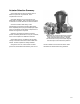
For rotary valves with reducers (swaged
installations), and other valve designs and fitting
styles, determine the F
p
factors by using the
procedure for determining F
p
, the piping geometry
factor.
4. Determine q
max
(the maximum flow rate at
given upstream conditions) or ΔP
max
(the
allowable sizing pressure drop).
The maximum or limiting flow rate (q
max
),
commonly called choked flow, is manifested by no
additional increase in flow rate with increasing
pressure differential with fixed upstream
conditions. In liquids, choking occurs as a result of
vaporization of the liquid when the static pressure
within the valve drops below the vapor pressure of
the liquid.
The IEC standard requires the calculation of an
allowable sizing pressure drop (ΔP
max
) to account
for the possibility of choked flow conditions within
the valve. The calculated ΔP
max
value is
compared with the actual pressure drop specified
in the service conditions, and the lesser of these
two values is used in the sizing equation. If it is
desired to use ΔP
max
to account for the possibility
of choked flow conditions it can be calculated
using the procedure for determining q
max
, the
maximum flow rate, or ΔP
max
, the allowable sizing
pressure drop. If it can be recognized that choked
flow conditions will not develop within the valve
ΔP
max
need not be calculated.