
Reference Manual


3−4
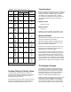
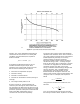
Figure 3-2. Liquid Critical Pressure Ratio Factor for Liquids Other Than Water
A2738-1
In order to assure uniformity and accuracy, the
procedures for both measuring flow parameters
and use in sizing are addressed by industrial
standards. The currently accepted standards are
sponsored by the ISA.
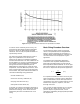
The basic test system configuration is shown in
figure 3-2. Specifications, accuracies, and
tolerances are given for all hardware installation
and data measurements such that coefficients can
be calculated to an accuracy of approximately 5%.
Fresh water at approximately 68°F is circulated
through the test valve at specified pressure
differentials and inlet pressures. Flow rate, fluid
temperature, inlet and differential pressure, valve
travel, and barometric pressure are all measured
and recorded. This yields sufficient information to
calculate the following sizing parameters:
D Flow coefficient (C
v
)
D Pressure recovery coefficient (F
L
)
D Piping correction factor (F
p
)
D Reynolds number factor (F
R
)
In general, each of these parameters depends on
the valve style and size, so multiple tests must be
performed accordingly. These values are then
published by the valve manufacturer for use in
sizing.
Basic Sizing Procedure Overview
The procedure by which valves are sized for
normal, incompressible flow is straightforward.
Again, to ensure uniformity and consistency, a
standard exists that delineates the equations and
correction factors to be employed for a given
application.
The simplest case of liquid flow application
involves the basic equation developed earlier.
Rearranging equation thirteen so that all of the
fluid and process related variables are on the right
side of the equation, we arrive at an expression for
the valve C
v
required for the particular application:
C
v
+
Q
P
1
*P
2
G
Ǹ
(15)
It is important to realize that valve size is only one
aspect of selecting a valve for a given application.
Other considerations include valve style and trim
characteristic. Discussion of these features can be
referenced in chapter 2, chapter 4, and other
thorough resources.
Once a valve has been selected and C
v
is known,
the flow rate for a given pressure drop, or the
pressure drop for a given flow rate, can be
predicted by substituting the appropriate quantities
into equation 16.