
Reference Manual


www.Fisher.com
*Some information in this introductory material has been extracted from ANSI/ISA
S75.01 standard with the permission of the publisher, the ISA.
{All terms are defined in the nomenclature section.
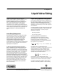
Chapter 3
Liquid Valve Sizing
Valves are selected and sized to perform a
specific function within a process system. Failure
to perform that given function in controlling a
process variable results in higher process costs.
Thus, valve sizing becomes a critical step to
successful process operation. The following
sections focus on correctly sizing valves for liquid
service: the liquid sizing equation is examined, the
nomenclature and procedures are explained, and
sample problems are solved to illustrate their
use.2-
Valve Sizing Background
Standardization activities for control valve sizing
can be traced back to the early 1960s when a
trade association, the Fluids Control Institute,
published sizing equations for use with both
compressible and incompressible fluids. The
range of service conditions that could be
accommodated accurately by these equations was
quite narrow, and the standard did not achieve a
high degree of acceptance.
In 1967, the International Society of America
(ISAt) established a committee to develop and
publish standard equations. The efforts of this
committee culminated in a valve sizing procedure
that has achieved the status of American National
Standards Institute (ANSI). Later, a committee of
the International Electrotechnical Commission
(IEC) used the ISA works as a basis to formulate
international standards for sizing control valves.*
Except for some slight differences in nomenclature
and procedures, the ISA and IEC standards have
been harmonized. ANSI/ISA Standard S75.01 is
harmonized with IEC Standards 534-2-1 and
534-2-2 (IEC Publications 534-2, Sections One
and Two for incompressible and compressible
fluids, respectively).
Liquid Sizing Equation Background
This section presents the technical substance of
the liquid sizing equations. The value of this lies in
not only a better understanding of the sizing
equations, but also in knowledge of their intrinsic
limitations and relationship to other flow equations
and conditions.
The flow equations used for sizing have their roots
in the fundamental equations, which describe the
behavior of fluid motion. The two principle
equations include the:
D Energy equation
D Continuity equation
The energy equation is equivalent to a
mathematical statement of the first law of
thermodynamics. It accounts for the energy
transfer and content of the fluid. For an
incompressible fluid (e.g. a liquid) in steady flow,
this equation can be written as:
ǒ
V
2
2g
c
)
P
ò
) gZ
Ǔ
* w ) q ) U + constant (1)
The three terms{ in parenthesis are all
mechanical, or available, energy terms and carry a
special significance. These quantities are all
capable of directly doing work. Under certain
conditions more thoroughly described later, this
quantity may also remain constant:
V
2
2g
c
)
P
ò
) gZ + constant (2)
This equation can be derived from purely
kinematic methods (as opposed to thermodynamic
methods) and is known as “Bernoulli’s equation”.
The other fundamental equation, which plays a
vital role in the sizing equation, is the continuity