
Reference Manual


2−7
available within a given package size. Additionally,
electric actuators are stiff, that is, resistant to valve
forces. This makes them an excellent choice for
good throttling control of large, high-pressure
valves.
Actuator Sizing
The last step in the selection process is to
determine the required actuator size.
Fundamentally, the process of sizing is to match
as closely as possible the actuator capabilities to
the valve requirements.
In practice, the mating of actuator and valve
requires the consideration of many factors. Valve
forces must be evaluated at the critical positions of
valve travel (usually open and closed) and
compared to actuator output. Valve force
calculation varies considerably between valve
styles and manufacturers. In most cases it is
necessary to consider a complex summation of
forces including:
D Static fluid forces
D Dynamic fluid forces and force gradients
D Friction of seals, bearings, and packing
D Seat loading
Although actuator sizing is not difficult, the great
variety of designs on the market and the ready
availability of vendor expertise (normally at no
cost) make detailed knowledge of the procedures
unnecessary.
Actuator Spring for Globe Valves
The force required to operate a globe valve
includes:
A. Force to overcome static unbalance of the
valve plug
B. Force to provide a seat load
C. Force to overcome packing friction
D. Additional forces required for certain specific
applications or constructions
Total force required = A + B + C + D
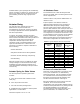
A. Unbalance Force
The unbalance force is that resulting from fluid
pressure at shutoff, and in the most general sense
can be expressed as:
Unbalance force = net pressure differential X net
unbalance area
Frequent practice is to take the maximum
upstream gauge pressure as the net pressure
differential unless the process design always
ensures a back pressure at the maximum inlet
pressure. Net unbalance area is the port area on a
single seated flow up design. Unbalance area may
have to take into account the stem area depending
on configuration. For balanced valves there is still
a small unbalance area. This data can be obtained
from the manufacturer. Typical port areas for
balanced valves flow up and unbalanced valves in
a flow down configuration are listed in table 2-1.
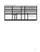
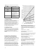
Table 2-1. Typical Unbalance Areas of Control Valves
Port Diameter,
Inches
Unbalance Area
Single-Seated
Unbalanced
Valves, In
2
Unbalance Area
Balanced Valves,
In
2
1/4 0.049 – – –
3/8 0.110 – – –
1/2 0.196 – – –
3/4 0.441 – – –
1 0.785 – – –
1 5/16 1.35 0.04
1 7/8 2.76 0.062
2 5/16 4.20 0.27
3 7/16 9.28 0.118
4 3/8 15.03 0.154
7 38.48 0.81
8 50.24 0.86
B. Force to Provide Seat Load
Seat load, usually expressed in pounds per lineal
inch or port circumference, is determined by
shutoff requirements. Use the guidelines in table
2-2 to determine the seat load required to meet
the factory acceptance tests for ANSI/FCI 70-2
and IEC 534-4 leak Classes II through VI.
Because of differences in the severity of service
conditions, do not construe these leak
classifications and corresponding leakage rates as
indicators of field performance. To prolong seat life
and shutoff capabilities, use a higher than
recommended seat load. If tight shutoff is not a
prime consideration, use a lower leak class.