
Reference Manual

2−3
An actuator made specifically for a control valve
eliminates the chance for a costly performance
mismatch. An actuator manufactured by the valve
vendor and shipped with the valve will eliminate
separate mounting charges and ensure easier
coordination of spare parts procurement.
Interchangeable parts among varied actuators are
also important to minimize spare-parts inventory.
Actuator Designs
There are many types of actuators on the market,
most of which fall into five general categories:
D Spring-and-diaphragm
D Pneumatic piston
D Rack and Pinion
D Electric motor
D Electro-hydraulic
Each actuator design has weaknesses, strong
points and optimum uses. Most actuator designs
are available for either sliding stem or rotary valve
bodies. They differ only by linkages or motion
translators; the basic power sources are identical.
Most rotary actuators employ linkages, gears, or
crank arms to convert direct linear motion of a
diaphragm or piston into the 90-degree output
rotation required by rotary valves. The most
important consideration for control valve actuators
is the requirement for a design that limits the
amount of lost motion between internal linkage
and valve coupling.
Rotary actuators are now available that employ
tilting pistons or diaphragms. These designs
eliminate most linkage points (and resultant lost
motion) and provide a safe, accurate and enclosed
package.
When considering an actuator design, it is also
necessary to consider the method by which it is
coupled to the drive shaft of the control valve.
Slotted connectors mated to milled shaft flats are
generally not satisfactory if any degree of
performance is required. Pinned connections, if
solidly constructed, are suitable for nominal torque
applications. A splined connector that mates to a
splined shaft end and then is rigidly clamped to the
shaft eliminates lost motion, is easy to
disassemble, and is capable of high torque.
Sliding stem actuators are rigidly fixed to valve
stems by threaded and clamped connections.
Because they don’t have any linkage points, and
their connections are rigid, they exhibit no lost
motion and have excellent inherent control
characteristics.
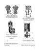
Spring-and-Diaphragm Actuators
The most popular and widely used control valve
actuator is the pneumatic spring-and-diaphragm
style. These actuators are extremely simple and
offer low cost and high reliability. They normally
operate over the standard signal ranges of 3 to 15
psi or 6 to 30 psi, and therefore, are often suitable
for throttling service using instrument signals
directly.
Many spring-and-diaphragm designs offer either
adjustable springs and/or wide spring selections to
allow the actuator to be tailored to the particular
application. Because they have few moving parts
that may contribute to failure, they are extremely
reliable. Should they ever fail, maintenance is
extremely simple. Improved designs now include
mechanisms to control the release of spring
compression, eliminating possible personnel injury
during actuator disassembly.
Use of a positioner or booster with a
spring-and-diaphragm actuator can improve
control, but when improperly applied, can result in
poor control. Follow the simple guidelines
available for positioner applications and look for:
D Rugged, vibration-resistant construction
D Calibration ease
D Simple, positive feedback linkages
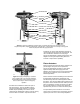
The overwhelming advantage of the
spring-and-diaphragm actuator is the inherent
provision for fail-safe action. As air is loaded on
the actuator casing, the diaphragm moves the
valve and compresses the spring. The stored
energy in the spring acts to move the valve back to
its original position as air is released from the
casing. Should there be a loss of signal pressure
to the instrument or the actuator, the spring can
move the valve to its initial (fail-safe) position.