
Reference Manual

1−17
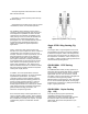
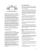
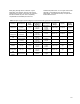
Figure 1-30. Typical Construction to Provide
Quick-Opening Flow Characteristic
A7100
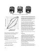
rate at the time of the change. The change in flow
rate observed regarding travel will be relatively
small when the valve plug is near its seat, and
relatively high when the valve plug is nearly wide
open. Therefore, a valve with an inherent
equal-percentage flow characteristic provides
precise throttling control through the lower portion
of the travel range and rapidly increasing capacity
as the valve plug nears the wide-open position.
Valves with equal-percentage flow characteristics
are used on pressure control applications, on
applications where a large percentage of the
pressure drop is normally absorbed by the system
itself with only a relatively small percentage
available at the control valve, and on applications
where highly varying pressure drop conditions can
be expected. In most physical systems, the inlet
pressure decreases as the rate of flow increases,
and an equal percentage characteristic is
appropriate. For this reason, equal percentage
flow is the most common valve characteristic.
Quick-Opening Flow
D A valve with a quick opening flow
characteristic provides a maximum change in flow
rate at low travels. The curve is essentially linear
through the first 40 percent of valve plug travel,
then flattens out noticeably to indicate little
increase in flow rate as travel approaches the
wide-open position. Control valves with
quick-opening flow characteristics are often used
for on/off applications where significant flow rate
must be established quickly as the valve begins to
open. As a result, they are often utilized in relief
valve applications. Quick-opening valves can also
be selected for many of the same applications for
which linear flow characteristics are
recommended. This is because the quick-opening
characteristic is linear up to about 70 percent of
maximum flow rate. Linearity decreases
significantly after flow area generated by valve
plug travel equals the flow area of the port. For a
typical quick-opening valve (figure 1-30), this
occurs when valve plug travel equals one-fourth of
port diameter.
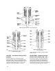
Valve Plug Guiding
Accurate guiding of the valve plug is necessary for
proper alignment with the seat ring and efficient
control of the process fluid. The common methods
used are listed below.
D Cage Guiding: The outside diameter of the
valve plug is close to the inside wall surface of the
cylindrical cage throughout the travel range. Since
the bonnet, cage, and seat ring are self-aligning
upon assembly, the correct valve plug and seat
ring alignment is assured when the valve closes
(figure 1-15).
D Top Guiding: The valve plug is aligned by a
single guide bushing in the bonnet, valve body
(figure 1-4), or by packing arrangement.
D Stem Guiding: The valve plug is aligned with
the seat ring by a guide bushing in the bonnet that
acts upon the valve plug stem (figure 1-3, left
view).
D Top-and-Bottom Guiding: The valve plug is
aligned by guide bushings in the bonnet and
bottom flange.
D Port Guiding: The valve plug is aligned by the
valve body port. This construction is typical for
control valves utilizing small-diameter valve plugs
with fluted skirt projections to control low flow rates
(figure 1-3, right view).
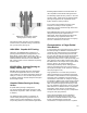
Restricted-Capacity Control Valve
Trim
Most control valve manufacturers can provide
valves with reduced- or restricted- capacity trim
parts. The reduced flow rate might be desirable for
any of the following reasons:
D Restricted capacity trim may make it possible
to select a valve body large enough for increased
future flow requirements, but with trim capacity
properly sized for present needs.
D Valves can be selected for adequate
structural strength, yet retain reasonable
travel/capacity relationship.
D Large bodies with restricted capacity trim can
be used to reduce inlet and outlet fluid velocities.
D Purchase of expensive pipeline reducers can
be avoided.
D Over-sizing errors can be corrected by use of
restricted capacity trim parts.