
Reference Manual

1−15
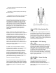
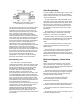
Figure 1-27. ENVIRO-SEAL Graphite
Packing System for Rotary Valves
W6125-1
placement of PTFE minimizes control problems,
reduces friction, promotes sealing, and extends
the cycle life of the packing set.
HIGH-SEAL Graphite ULF Packing
Identical to the ENVIRO-SEAL graphite ULF
packing system below the packing follower, the
HIGH-SEAL system utilizes heavy-duty, large
diameter Belleville springs. These springs provide
additional follower travel and can be calibrated
with a load scale for a visual indication of packing
load and wear.
ENVIRO-SEAL Graphite Packing for
Rotary Valves (Fig. 1-27)
ENVIRO-SEAL graphite packing is designed for
environmental applications from −6°C to 316°C
(20°F to 600°F) or for those applications where fire
safety is a concern. It can be used with pressures
to 103 bar (1500 psi) and still satisfy the 500 ppmv
EPA leakage criteria.
Graphite Ribbon Packing for Rotary
Valves
Graphite ribbon packing is designed for
non-environmental applications that span a wide
temperature range from −198°C to 538°C (−325°F
to 1000°F).
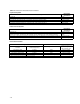
The following table provides a comparison of
various sliding-stem packing selections and a
relative ranking of seal performance, service life,
and packing friction for environmental applications.
Braided graphite filament and double PTFE are
not acceptable environmental sealing solutions.
The following applies to rotary valves. In the case
of rotary valves, single PTFE and graphite ribbon
packing arrangements do not perform well as
fugitive emission sealing solutions.
The control of valve fugitive emissions and a
reduction in industry’s cost of regulatory
compliance can be achieved through these stem
sealing technologies.
While ENVIRO-SEAL packing systems have been
designed specifically for fugitive emission
applications, these technologies should also be
considered for any application where seal
performance and seal life have been an ongoing
concern or maintenance cost issue.
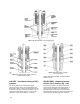
Characterization of Cage-Guided
Valve Bodies
In valve bodies with cage-guided trim, the shape of
the flow openings or windows in the wall of the
cylindrical cage determines flow characterization.
As the valve plug is moved away from the seat
ring, the cage windows are opened to permit flow
through the valve. Standard cages have been
designed to produce linear, equal-percentage, and
quick-opening inherent flow characteristics. Note
the differences in the shapes of the cage windows
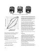
shown in figure 1-28. The flow rate/travel
relationship provided by valves utilizing these
cages is equivalent to the linear, quick-opening,
and equal-percentage curves shown for contoured
valve plugs (figure 1-29).
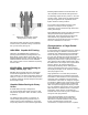
Cage-guided trim in a control valve provides a
distinct advantage over conventional valve body
assemblies in that maintenance and replacement
of internal parts is simplified. The inherent flow
characteristic of the valve can easily be changed
by installing a different cage. Interchange of cages
to provide a different inherent flow characteristic
does not require changing the valve plug or seat
ring. The standard cages shown can be used with
either balanced or unbalanced trim constructions.
Soft seating, when required, is available as a
retained insert in the seat ring and is independent
of cage or valve plug selection.
Cage interchangeability can be extended to
specialized cage designs that provide noise
attenuation or combat cavitation. These cages
furnish a modified linear inherent flow
characteristic, but require flow to be in a specific