
Reference Manual


18−3
trim can be designed to handle the cavitating
conditions at startup and then standard equal
percentage or linear characteristic for steady-state
conditions to maximize capacity. Another common
issue in both the startup and regulator valves is to
see them operated below the minimum operating
point. This can cause “gear-toothing” damage on
the plug.
Design Considerations:
D Cavitation
D Tight shutoff (Class V)
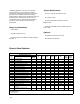
D Typical process conditions are 800-1200 psig
and 200-400 °F
Typical Specifications:
D easy-e, HP, or EH
D Cavitrol III Trim
D HTS1 option with improved pressure balance
seal
D FIELDVUE digital valve controller with low
travel cutoff
Optional:
D NotchFlo or DST
D Protected inside seat
Steam Generation
The number and types of boilers used for steam
production varies considerably from mill to mill.
Figure 18-1 indicates a simple system consisting
of one power boiler and one recovery boiler
discharging into a common high pressure
superheated steam header. For this system, the
recovery boiler is base loaded at a constant flow
of black liquor fuel with steam flow and pressure
allowed to fluctuate. The steam header pressure
(typically 1000-1500 psig) is controlled by varying
the fuel input to the power boiler. Power boiler fuel
is typically base loaded with bark or hog fuel and
supplemented with coal, oil, or gas.
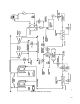
Figure 18-2 provides an enlarged view of the
upper convective section of a boiler. BFW enters
the economizer at 800-1200 psig and 200-400°F
before flowing to the steam drum of the generating
section. As mentioned earlier, demineralized water
is used in boilers due to high operating pressures
and temperatures. Even so, as saturated steam
leaves the steam drum, trace amounts of solids
are left behind. These solids must be removed via
continuous bleed or blowdown of a small amount
of water to prevent accumulation. The mud drum
is also a low point for solids to settle and has
provision for intermittent blowdown to prevent
accumulation.
Saturated steam leaving the steam drum passes
through the superheater section for further heating
and moisture evaporation. Most superheaters
consist of a primary and secondary section.
Attemperation or desuperheating is used between
the sections to control final temperature and
prevent overheating of tubes. The source of water
must be of demineralized quality to prevent
accumulation of deposits on the inside of the
tubes. A common source is boiler feedwater from
the discharge of the boiler feedwater pump.
A vent is indicated on the superheated steam
outlet before the high pressure steam header. This
vent may serve multiple purposes. One use is to
clear the superheater of any moisture during
start-up. This is to assure no water droplets reach
the steam turbine. A second function is pressure
relief in case an alarm indicates a build-up of
pressure. A final function may involve setting the
valve to open on high pressure just before the
spring operated safety valve would lift. Due to high
flow and pressure drop creating excessive noise,
the valve is often used in series with a diffuser
and/or silencer. Also shown in figure 18-2 is a
valve for controlling the flow of steam to the
sootblowers.
Sootblower Valve
When firing fuels such as coal, oil, biomass, or
other waste products, fouling of the boiler tubes
becomes a concern. Deposits from the
combustion process can collect on the heat
exchanging tubes reducing thermal efficiency and
can cause operational difficulties. In order to keep
the unit operating, an online cleaning method must
be used. This is usually accomplished by using
what are called sootblowers. Sootblowers utilize
flowing media such as water, air, or steam to
remove deposits from boiler tubes. Widespread
use of water has been limited due to the possibility
of thermal shock on the tube banks so steam is
the most common media. There are several
different types of sootblowers used. Wall blowers