
Reference Manual

1−8
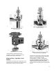
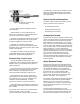
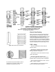
Figure 1-13. Popular Varieties of
Bolted Flange Connections
A7098
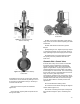
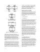
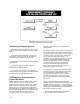
Figure 1-14. Common Welded End Connections
A7099
finished with concentric circular grooves for
precise sealing and resistance to gasket blowout.
This kind of flange is used with a variety of gasket
materials and flange materials for pressures
through the 6000 psig (414 bar) pressure range
and for temperatures through 1500°F (815°C).
This style of flanging is normally standard on Class
250 cast iron bodies and all steel and alloy steel
bodies.
The ring-type joint flange is similar in looks to the
raised-face flange except that a U-shaped groove
is cut in the raised-face concentric with the valve
opening. The gasket consists of a metal ring with
either an elliptical or octagonal cross-section.
When the flange bolts are tightened, the gasket is
wedged into the groove of the mating flange and a
tight seal is made. The gasket is generally soft iron
or Monelt, but is available in almost any metal.
This makes an excellent joint at high pressures
and is used up to 15,000 psig (1034 bar),
however, it is generally not used at high
temperatures. It is furnished only on steel and
alloy valve bodies when specified.
Welding End Connections
Welding ends on control valves (figure 1-14) are
leak-tight at all pressures and temperatures, and
are economical in first cost. Welding end valves
are more difficult to take from the line and are
limited to weldable materials. Welding ends come
in two styles:
D Socket welding
D Buttwelding
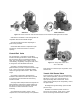
The socket welding ends are prepared by boring in
a socket at each end of the valve with an inside
diameter slightly larger than the pipe outside
diameter. The pipe slips into the socket where it
butts against a shoulder and then joins to the valve
with a fillet weld. Socket welding ends in a given
size are dimensionally the same regardless of pipe
schedule. They are usually furnished in sizes
through NPS 2.
The buttwelding ends are prepared by beveling
each end of the valve to match a similar bevel on
the pipe. The two ends are then butted to the
pipeline and joined with a full penetration weld.
This type of joint is used on all valve styles and the
end preparation must be different for each
schedule of pipe. These are generally furnished for
control valves in NPS 2-1/2 and larger. Care must
be exercised when welding valve bodies in the
pipeline to prevent excessive heat transmitted to
valve trim parts. Trims with low-temperature
composition materials must be removed before
welding.
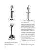
Valve Body Bonnets
The bonnet of a control valve is the part of the
body assembly through which the valve plug stem
or rotary shaft moves. On globe or angle bodies, it
is the pressure retaining component for one end of
the valve body. The bonnet normally provides a
means of mounting the actuator to the body and
houses the packing box. Generally, rotary valves
do not have bonnets. (On some rotary-shaft
valves, the packing is housed within an extension
of the valve body itself, or the packing box is a
separate component bolted between the valve
body and bonnet.)