
Reference Manual


11−3
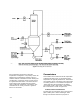
below the lower tube sheet. As it boils or
percolates, a thin film of liquor rises up the inside
of the tube or plate. The liquor overflows the upper
tube sheet and falls via a downcomer pipe to a
transfer pump. The vapor exits via a centrifugal
separator and is piped to the next effect. This
design provides high evaporation capacity at a low
cost, but is sensitive to scaling and plugging above
50% solids.
Although the rising film design is predominant in
installed base, the falling film design has become
increasingly popular since the early 1980’s and is
now the most common type of evaporator. This
design looks like an upside-down rising film
evaporator (vapor dome at the bottom and the
tube bundle extending upward). As its name
implies, liquor is fed into the upper tube sheet area
and flows as a thin film down the inside of the
tubes. The liquor collects in the lower dome and is
discharged from the evaporator body. Since the
liquor flow is in the same direction as gravity and
flowing in a thin film, higher heat transfer
coefficients are realized. The higher coefficients
allow for lower temperature differentials (vapor vs.
liquor) resulting in the ability to achieve higher
solids concentration and less scaling than a LTV
design. The main disadvantage is associated with
the high pumping cost of multiple-pass forced
circulation employed on most falling film designs.
A number of alternative systems and variations to
the classical multiple effect system has emerged
recently in an effort to obtain higher solids
concentrations, and reduce fouling of heating
surfaces. Some of the variations to the classical
sequence involve changing the feed liquor input
location and using lower solids liquor to wash
surfaces where higher solids liquor are normally
made. This extends the time between general
washings or “boilouts”.
A recent alternative system involves combining
rising and falling film evaporator bodies in a
multiple effect system. In this design, the first two
or three effects are falling film evaporators and the
last three or four effects are rising film
evaporators. This gives the advantage of pumping
energy conservation on the “back end” where
solids and scaling potential are lower and the
resistance to fouling on the “front end” as solids
increase.
Another system has emerged in recent years
known as mechanical vapor recompression
(MVR). This system typically employs a single
evaporator body, a compressor, and heat
exchangers. This system reuses vapors by raising
the temperature and pressure with a compressor.
It is used mainly where steam supply is
inadequate and electrical power is economical.
Auxiliary Equipment
Various pieces of auxiliary equipment are required
to support the operation of an evaporator set.
Some of this equipment is briefly described below:
D Soap Skimming/Removal
Soap or tall oil soap is composed of fatty and resin
acids found in wood products. During evaporation,
the soap will not stay dissolved beyond 25 - 30%
solids concentration. Failure to remove the soap
results in excessive foaming and a lower efficiency
for the entire recovery cycle. Typically, liquor
leaving the fourth effect is diverted to a skimming
tank where the soap is removed for processing.
After the soap is removed, the liquor is transferred
to the third effect to continue evaporation.
D Flash Tanks
Flash tanks are used to recover heat from flashing
liquor or condensate to a lower pressure. Typical
flash tank locations are product liquor and clean
steam condensate from the first effect. The flash
steam is then used for process heating.
D Condenser and NCG Removal
As mentioned earlier, a condenser is used to
maintain a vacuum at the “back end” of the
evaporator set. The condenser is connected to the
vapor duct from the sixth effect. The condensed
vapors from the sixth effect, referred to as foul
condensate, contains contaminants such as sulfur
gases and black liquor organics. These
contaminants are removed by a steam stripping
system since they create odor and pollution
problems.
Non-condensible gases (NCG) such as hydrogen
sulfide, mercaptans, and carbon dioxide also tend
to accumulate in the condenser. These gases are
removed with a steam or air fed ejector system
and sent to an incinerator. Failure to remove these
gases will limit an evaporator set by reducing the
available vacuum and temperature differential.
D Foul Condensate Stripping