
Reference Manual

1−7
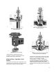
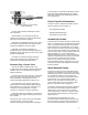
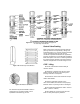
Figure 1-12. Sectional of Eccentric-Plug
Control Valve Body
W4170-4
D They utilize standard diaphragm or piston
rotary actuators.
D Ball remains in contact with seal during
rotation, which produces a shearing effect as the
ball closes and minimizes clogging.
D Bodies are available with either heavy-duty or
PTFE-filled composition ball seal ring to provide
excellent rangeability in excess of 300:1.
D Bodies are available in flangeless or
flanged-body end connections. Both flanged and
flangeless valves mate with Class 150, 300, or 600
flanges or DIN flanges.
D Valves are capable of energy absorbing
special attenuating trim to provide improved
performance for demanding applications.
Eccentric-Plug Control Valve
D Valve assembly combats erosion. The
rugged body and trim design handle temperatures
to 800°F (427°C) and shutoff pressure drops to
1500 psi (103 bar).
D Path of eccentric plug minimizes contact with
the seat ring when opening, thus reducing seat
wear and friction, prolonging seat life, and
improving throttling performance (figure 1-12).
D Self-centering seat ring and rugged plug
allow forward or reverse-flow with tight shutoff in
either direction. Plug, seat ring, and retainer are
available in hardened materials, including
ceramics, for selection of erosion resistance.
D Designs offering a segmented V-notch ball in
place of the plug for higher capacity requirements
are available.
This style of rotary control valve is well-suited for
control of erosive, coking, and other
hard-to-handle fluids, providing either throttling or
on-off operation. The flanged or flangeless valves
feature streamlined flow passages and rugged
metal-trim components for dependable service in
slurry applications.
Control Valve End Connections
The three common methods of installing control
valves in pipelines are by means of:
D Screwed pipe threads
D Bolted gasketed flanges
D Welded end connections
Screwed Pipe Threads
Screwed end connections, popular in small control
valves, are typically more economical than flanged
ends. The threads usually specified are tapered
female National Pipe Thread (NPT) on the valve
body. They form a metal-to-metal seal by wedging
over the mating male threads on the pipeline ends.
This connection style, usually limited to valves not
larger than NPS 2, is not recommended for
elevated temperature service. Valve maintenance
might be complicated by screwed end connections
if it is necessary to take the body out of the
pipeline. This is because the valve cannot be
removed without breaking a flanged joint or union
connection to permit unscrewing the valve body
from the pipeline.
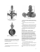
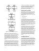
Bolted Gasketed Flanges
Flanged end valves are easily removed from the
piping and are suitable for use through the range
of working pressures for which most control valves
are manufactured (figure 1-13). Flanged end
connections can be used in a temperature range
from absolute zero to approximately 1500°F
(815°C). They are used on all valve sizes. The
most common flanged end connections include
flat-face, raised-face, and ring-type joint.
The flat face variety allows the matching flanges to
be in full-face contact with the gasket clamped
between them. This construction is commonly
used in low pressure, cast iron, and brass valves,
and minimizes flange stresses caused by initial
bolting-up force.
The raised-face flange features a circular
raised-face with the inside diameter the same as
the valve opening, and the outside diameter less
than the bolt circle diameter. The raised-face is