
Reference Manual


10A −7
withstand digester-like pressures and so the relief
valve will pop if the outlet for gas-off is plugged
with pulp. Similarly, flashed vapor to a condensing
device can create sufficient vacuum to collapse a
blow tank. The vacuum relief valve provides a
margin of safety against such an occurrence.
From the blow tank the brown stock is pumped to
washing and screening stages.
Control Valve Selection
Digester Capping Valve
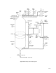
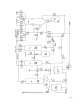
The chips are conveyed to the chip chute which is
mounted directly to the capping valve (see figures
10A-1 and 10A-2). One of the most important
valves, this valve is used to automate the chip
filling operation. This is an erosive service as the
chips impinge on the sides of the body and ball, so
hardened materials and trim must be used. In
addition, tight shutoff is necessary to ensure the
appropriate pressure can be reached within the
digester for chip cooking.
General Service Valves
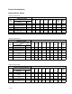
Refer to figure 10A-1.
PROCESS FISHER CONTROL VALVE PRODUCT DESIGN
Valve
Tag #
DIRECT STEAMED
BATCH DIGESTER
V150 V300 V500 CV500 ED/ET
Typical
Valve Size
Application
Description
Control
Function
HV-1 Liquor fill O/O P 10’’
FV-1 White liquor to digester T S S P 8’’
FV-2 Black liquor to digester T S S P 8’’
HV-2 Blow back steam valve O/O P 2’’
PV-1 Gas off T P 3’’
TV-1 Cooking valve T S P 8’’
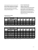
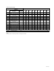
Refer to figure 10A-2.
PROCESS FISHER CONTROL VALVE PRODUCT DESIGN
Valve
Tag #
INDIRECTLY STEAMED
BATCH DIGESTER
V150 V300 V500 CV500 ED/ET
Typical
Valve Size
Application
Description
Control
Function
HV-1 Liquor fill O/O S P 10’’
FV-1 White liquor to digester T S P 8’’
FV-2 Black liquor to digester T S P 8’’
HV-2 Blow back valve O/O P 2’’
PV-1 Gas off T P 3’’
TV-1 Indirect steam valve T S P 3’’
FV-3 Digester top recirculation T P 8’’
FV-4 Digester bottom recirculation T P 8’’
TV-2 Condensate return T P S 3’’
TV-3 Direct steam valve T S P 6’’
CODE:
P = Primary selection, S = Secondary selection, T = Throttling, O/O = On/Off