
Reference Manual


7−12
Control of the HP bypass is normally initiated via
feedback input signals from the main steam
pressure and the cold reheat temperature. The
ratio of steam to spraywater is normally inversely
proportional to the respective valve position,
especially during startup and shutdown. This is
because startup conditions normally require large
valve Cvs, due to the large specific volumes
associated with low pressures at high
temperatures, even though flow is greatly
reduced.
During trip conditions, the opposite is true, and
large quantities of spraywater are required at
lower valve openings. For this situation, special
control algorithms usually are incorporated into the
control system to provide independent feedforward
control. This is especially important during a trip
sequence where time of response is critical to
maintain system integrity, performance, and
component protection.
Spraywater for cooling is normally obtained from
the boiler feed pump discharge and is regulated by
an external spraywater control valve that is
properly sized to handle the required flow and
pressure drop.
Hot-Reheat and Low Pressure
Bypass
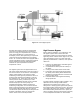
During startup, shutdown, or on turbine trip, the
HRH and LP bypass systems direct steam from
the hot reheat line to the condenser, thus
bypassing the IP and LP turbine sections (figure
7-12). The major advantages of such an action
have been generally outlined above. However,
more specific duties are:
1. Pressure and temperature controlled
bypassing of the IP and LP turbines.
2. Controlling pressure build-up in the boiler
reheat section.
3. Prevention of condensate losses during load
trips and minor disturbances.
4. Protecting the condenser against excessive
pressure, temperature, and enthalpy
excursions during bypass operation.
In contrast to the HP bypass, the HRH and LP
bypass valves only fail closed as a failure mode.
While it is important to control the hot reheat
pressure, it is even more critical to protect the
condenser against damage from uncontrolled or
improper admission of steam. The condenser
manufacturer interfaces specific condenser control
permissives with these bypass control systems. If
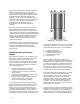
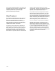
Figure 7-13. TBX WhisperFlo Sparger.
W8684-2
any of these permissives is not met or is exceeded
during bypass operation, the valve is quickly shut.
These permissives include, but are not limited to:
1. Condensate level high
2. Condenser temperature high
3. Condenser pressure high
4. Spraywater pressure low
5. Loss of coolant
Another added challenge of the HRH and LP
bypass system is to properly control the amount of
backpressure on the bypass valves. A condenser
or condenser duct, which is downstream of these
bypass valves, typically operates at a vacuum in
the range of 1 - 3 psia. Given this scenario, it is
crucial to create backpressure in order to maintain
a desired velocity within reasonable pipe sizes.
A second challenge to this application is to create
these desired conditions while minimizing the
noise generated by this process. Dumping high
velocity steam into a low pressure, thin wall
condenser/turbine exhaust duct requires careful
evaluation in order to assure steam jets do not
converge. Hole spacing within the sparger and
sparger placement within the duct are critical for
maintaining low noise levels.
A typical bypass to condenser installation requires
a steam conditioning valve to control pressure and
temperature, a spraywater valve to regulate the
water supply, and a downstream TBX sparger to
create backpressure. Low noise WhisperFlo trim