
Reference Manual


7−11
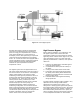
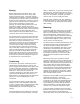
Figure 7-12. Turbine Bypass System
E0866
the latest technology in pressure-reducing/low
noise trim to handle the flow and reduction of
pressure energy to acceptable levels. However,
since steam throttling in a control valve is an
isenthalpic process, desuperheating is required to
control the discharge temperature and enthalpy
levels. As a result, the valves are equipped with a
special spraywater injection system that produces
a finely atomized and evenly distributed water
interface for rapid vaporization and steam
temperature control.
The bypass system can be supplied with one or
two control inputs depending on the role it plays in
the control scheme. If the valve is used solely for
startup and shutdown, it will receive a single
modulating control signal to position the trim as a
function of the startup and shutdown curves for
the respective unit. If the valve must also act to
relieve pressure during a turbine trip or load
rejection, an additional discrete input is included
that will ramp open the valve quickly to a
predetermined position, before reverting to a
modulating configuration in accordance with the
boiler control requirements. Fast positioning speed
and resultant alternate flow path are critical to
counteract the pressure build-up resulting from the
isolation of the boiler piping circuit when the
turbine valves close in this trip situation.
High Pressure Bypass
During startup, shutdown, or on turbine trip, the
HP bypass system directs steam from the
superheater outlet to the cold reheat line, thereby
bypassing the HP turbine section (figure 7-9). The
major advantages of such an action have been
generally outlined above. However, more specific
duties are:
1. Pressure and temperature controlled bypass
of the HP turbine section.
2. Controlled main steam pressure build-up in
the boiler.
3. Cooling of the reheat section of the boiler.
4. Prevention of the opening of spring-loaded
HP safety valves during minor disturbances.
5. Avoidance of condensate loss and noise from
blowing safety valves.
6. Protection of the boiler against exceeding
design pressures.
The failure mode of the HP bypass system is very
dependent on local design codes and the
performance scenario for the system. If it is
designed as a safety bypass system and replaces
the standard safety relief valve function, the valves
must always fail in the open position. However, if
the standard safety relief valves are in place, the
valve is normally required to fail closed, especially
in over-temperature situations on drum boilers.