CONTROL VALVE SOURCEBOOK PULP & PAPER
Copyright © 2011 Fisher Controls International LLC All Rights Reserved. Fisher, ENVIRO-SEAL, Whisper Trim, Cavitrol, WhisperFlo, Vee‐Ball, Control‐Disk, NotchFlo, easy‐e and FIELDVUE are marks owned by Fisher Controls International LLC, a business of Emerson Process Management. The Emerson logo is a trademark and service mark of Emerson Electric Co. All other marks are the property of their respective owners.
Table of Contents Introduction v Chapter 1 Control Valve Selection 1-1 Chapter 2 Actuator Selection 2-1 Chapter 3 Liquid Valve Sizing 3-1 Chapter 4 Cavitation & Flashing 4-1 Chapter 5 Gas Valve Sizing 5-1 Chapter 6 Control Valve Noise 6-1 Chapter 7 Steam Conditioning 7-1 Chapter 8 Process Overview 8-1 Chapter 9 Pulping 9-1 Chapter 10A Batch Digesters 10A-1 Chapter 10B Continuous Digesters 10B-1 Chapter 11 Black Liquor Evaporators/Concentrators 11-1 Chapter 12 Kraft Re
iv
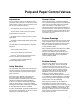
Pulp and Paper Control Valves Introduction Control Valves This sourcebook’s intent is to introduce a pulp and paper mill’s processes, as well as the use of control valves in many of the processes found in the mill. It is intended to help you: D Learn where control valves are typically located within each process Valves described within a chapter are labeled and numbered corresponding to the identification used in the process flow chart for that chapter.
vi
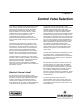
Chapter 1 Control Valve Selection In the past, a customer simply requested a control valve and the manufacturer offered the product best-suited for the job. The choices among the manufacturers were always dependent upon obvious matters such as cost, delivery, vendor relationships, and user preference. However, accurate control valve selection can be considerably more complex, especially for engineers with limited experience or those who have not kept up with changes in the control valve industry.
Valve Types and Characteristics The control valve regulates the rate of fluid flow as the position of the valve plug or disk is changed by force from the actuator. To do this, the valve must: D Contain the fluid without external leakage. D Have adequate capacity for the intended service. D Be capable of withstanding the erosive, corrosive, and temperature influences of the process.
W0540 W0971 Figure 1-4. High Pressure Globe-Style Control Valve Body Figure 1-2. Flanged Angle-Style Control Valve Body W9756 W0992-4 Figure 1-3. Bar Stock Valve Body cage-guided trim, bolted body-to-bonnet connection, and others. Flanged versions are available with ratings to Class 2500. Balanced-Plug Cage-Style Valve Bodies This popular valve body style, single-ported in the sense that only one seat ring is used, provides the advantages of a balanced valve plug often Figure 1-5.
liquid service. The flow direction depends upon the intended service and trim selection, with unbalanced constructions normally flow-up and balanced constructions normally flow-down. Port-Guided Single-Port Valve Bodies D Usually limited to 150 psi (10 bar) maximum pressure drop. D Susceptible to velocity-induced vibration. D Typically provided with screwed in seat rings which might be difficult to remove after use.
W8380 Figure 1-9. Eccentric-Disk Rotary-Shaft Control Valve W9045-1 Figure 1-7. Three Way Valve with Balanced Valve Plug D Offer an economic advantage, particularly in larger sizes and in terms of flow capacity per dollar investment. D Mate with standard raised-face pipeline flanges. D Depending on size, might require high output or oversized actuators due to valve size valves or large operating torques from large pressure drops.
W9425 W9418 WAFER STYLE SINGLE FLANGE STYLE Figure 1-10. Fisher Control-Disk Valve with 2052 Actuator and FIELDVUE DVC6200 Digital Valve Controller D Bodies are available in sizes through NPS 24 compatible with standard ASME flanges. D Utilize standard pneumatic diaphragm or piston rotary actuators. D Standard flow direction is dependent upon seal design; reverse flow results in reduced capacity.
on-off operation. The flanged or flangeless valves feature streamlined flow passages and rugged metal-trim components for dependable service in slurry applications. Control Valve End Connections W4170-4 Figure 1-12. Sectional of Eccentric-Plug Control Valve Body The three common methods of installing control valves in pipelines are by means of: D Screwed pipe threads D They utilize standard diaphragm or piston rotary actuators.
or Monelt, but is available in almost any metal. This makes an excellent joint at high pressures and is used up to 15,000 psig (1034 bar), however, it is generally not used at high temperatures. It is furnished only on steel and alloy valve bodies when specified. Welding End Connections Welding ends on control valves (figure 1-14) are leak-tight at all pressures and temperatures, and are economical in first cost.
guides the valve plug to ensure proper valve plug stem alignment with the packing. As mentioned previously, the conventional bonnet on a globe-type control valve houses the packing. The packing is most often retained by a packing follower held in place by a flange on the yoke boss area of the bonnet (figure 1-15). An alternate packing retention means is where the packing follower is held in place by a screwed gland (figure 1-3).
W6434 W0667-2 Figure 1-16. Extension Bonnet Figure 1-18. ENVIRO-SEALt Bellows Seal Bonnet Bellows Seal Bonnets Bellows seal bonnets (figure 1-18) are used when no leakage (less than 1x10⁻⁶ cc/sec of helium) along the stem can be tolerated. They are often used when the process fluid is toxic, volatile, radioactive, or highly expensive. This special bonnet construction protects both the stem and the valve packing from contact with the process fluid.
B2565 Figure 1-21. Comprehensive Packing Material Arrangements for Globe-Style Valve Bodies Control Valve Packing Most control valves use packing boxes with the packing retained and adjusted by a flange and stud bolts (figure 1-27). Several packing materials can be used depending upon the service conditions expected and whether the application requires compliance to environmental regulations.
B2566 Figure 1-22. Measurement Frequency for Valves Controlling Volatile Organic Chemicals (VOC) Laminated and Filament Graphite D Suitable for high temperature nuclear service or where low chloride content is desirable (Grade GTN). D Provides leak-free operation, high thermal conductivity, and long service life, but produces high stem friction and resultant hysteresis. D Impervious to most hard-to-handle fluids and high radiation. D Suitable temperature range: Cryogenic temperatures to 1200°F (649°C).
D Proper alignment of the valve stem or shaft within the bonnet bore. D Applying a constant packing stress through Belleville springs. D Minimizing the number of seal rings to reduce consolidation, friction, and thermal expansion. The traditional valve selection process meant choosing a valve design based upon its pressure and temperature capabilities as well as its flow characteristics and material compatibility.
A6163 Figure 1-24. ENVIRO-SEAL PTFE Packing System 39B4612-A Figure 1-25. ENVIRO-SEAL Duplex (PTFE and Graphite) Packing System Figure 1-26. ENVIRO-SEAL Graphite ULF Packing System carbon fiber reinforced TFE, is suited to 260°C (500°F) service. KALREZt Valve Stem Packing (KVSP) systems ENVIRO-SEAL Graphite Ultra Low Friction (ULF) Packing (Fig. 1-26) The KVSP pressure and temperature limits referenced are for Fisher valve applications only. KVSP with PTFE is suited to environmental use up to 24.
Braided graphite filament and double PTFE are not acceptable environmental sealing solutions. The following applies to rotary valves. In the case of rotary valves, single PTFE and graphite ribbon packing arrangements do not perform well as fugitive emission sealing solutions. The control of valve fugitive emissions and a reduction in industry’s cost of regulatory compliance can be achieved through these stem sealing technologies. W6125-1 Figure 1-27.
W0958 W0959 QUICK OPENING W0957 LINEAR EQUAL PERCENTAGE Figure 1-28. Characterized Cages for Globe-Style Valve Bodies Valve plugs are designed for either two-position or throttling control. In two-position applications, the valve plug is positioned by the actuator at either of two points within the travel range of the assembly. In throttling control, the valve plug can be positioned at any point within the travel range as dictated by the process requirements. Figure 1-29.
Valve Plug Guiding Accurate guiding of the valve plug is necessary for proper alignment with the seat ring and efficient control of the process fluid. The common methods used are listed below. A7100 Figure 1-30. Typical Construction to Provide Quick-Opening Flow Characteristic rate at the time of the change. The change in flow rate observed regarding travel will be relatively small when the valve plug is near its seat, and relatively high when the valve plug is nearly wide open.
Conventional globe-style valve bodies can be fitted with seat rings with smaller port size than normal and valve plugs sized to fit those smaller ports. Valves with cage-guided trim often achieve the reduced capacity effect by utilizing valve plug, cage, and seat ring parts from a smaller valve size of similar construction and adapter pieces above the cage and below the seat ring to mate those smaller parts with the valve body (figure 1-28).
Flow Characteristic The next selection criterion, “inherent flow characteristic”, refers to the pattern in which the flow at constant pressure drop changes according to valve position. Typical characteristics are quick-opening, linear, and equal-percentage. The choice of characteristic may have a strong influence upon the stability or controllability of the process (see table 1-3), as it represents the change of valve gain relative to travel.
The threads usually specified are tapered female NPT on the valve body. They form a metal-to-metal seal by wedging over the mating male threads on the pipeline ends. This connection style is usually limited to valves not larger than NPS 2, and is not recommended for elevated temperature service. Valve maintenance might be complicated by screwed end connections if it is necessary to take the body out of the pipeline.
After going through all the criteria for a given application, the selection process may point to several types of valves. From there on, selection becomes a matter of price versus capability, coupled with the inevitable personal and institutional preferences. As no single control valve package is cost-effective over the full range of applications, it is important to keep an open mind to alternative choices. Table 1-2.
Table 1-3.
Table 1-4. Control Valve Leakage Standards ANSI B16.104-1976 Maximum Leakage Test Medium Pressure and Temperature Class II 0.5% valve capacity at full travel Air Service ΔP or 50 psid (3.4 bar differential), whichever is lower, at 50_ or 125_F (10_ to 52_C) Class III 0.1% valve capacity at full travel Air Service ΔP or 50 psid (3.4 bar differential), whichever is lower, at 50_ or 125_F (10_ to 52_C) Class IV 0.01% valve capacity at full travel Air Service ΔP or 50 psid (3.
1−24
Chapter 2 Actuator Selection The actuator is the distinguishing element that differentiates control valves from other types of valves. The first actuated valves were designed in the late 19th century. Today, they would be better described as regulators since they operated directly from the process fluid. These “automatic valves” were the mainstay of industry through the early 1930s. It was at this time that the first pneumatic controllers were used.
Actuator designs are available with a choice of failure mode between failing open, failing closed, or holding in the last position. Many actuator systems incorporate failure modes at no extra cost. For example, spring-and-diaphragm actuators are inherently fail open or closed, while electric operators typically hold their last position. Torque or Thrust Requirements An actuator must have sufficient thrust or torque for the prescribed application.
An actuator made specifically for a control valve eliminates the chance for a costly performance mismatch. An actuator manufactured by the valve vendor and shipped with the valve will eliminate separate mounting charges and ensure easier coordination of spare parts procurement. Interchangeable parts among varied actuators are also important to minimize spare-parts inventory.
DIAPHRAGM CASING DIAPHRAGM DIAPHRAGM PLATE LOWER DIAPHRAGM CASING ACTUATOR SPRING ACTUATOR STEM SPRING SEAT SPRING ADJUSTOR STEM CONNECTOR YOKE TRAVEL INDICATOR DISK INDICATOR SCALE W0364-1 W0363-1 Figure 2-1. Spring-and-diaphragm actuators offer an excellent first choice for most control valves. They are inexpensive, simple and have built-in, fail-safe action. Pictured above are cutaways of the popular Fisher 667 (left) and Fisher 657 (right) actuators.
W9589-1 W9588-1 Figure 2-3. The Fisher 2052 spring-anddiaphragm actuator has many features to provide precise control. The splined actuator connection features a clamped lever and single-joint linkage to help eliminate lost motion. W7447 Figure 2-5. Spring fail-safe is present in this piston design. The Fisher 585C is an example of a spring-bias piston actuator. Process pressure can aid fail-safe action, or the actuator can be configured for full spring-fail closure. W3827−1 Figure 2-4.
actuator and operate it much like a spring-anddiaphragm. These designs use a single-acting positioner that loads the piston chamber to move the actuator and compress the spring. As air is unloaded, the spring forces the piston back. These designs use large, high output springs that are capable of overcoming the fluid forces in the valve. The alternative design uses a much smaller spring and relies on valve fluid forces to help provide the fail-safe action.
available within a given package size. Additionally, electric actuators are stiff, that is, resistant to valve forces. This makes them an excellent choice for good throttling control of large, high-pressure valves. A.
Table 2-2.
Torque Equations Table 2-3. Typical Packing Friction Values (Lb) Stem Size (Inches) ANSI Class PTFE Packing Single Double 5/16 All 20 30 3/8 125 150 250 300 38 56 1/2 600 900 1500 125 150 250 300 50 75 600 900 1500 2500 5/8 3/4 Graphite Ribbon/ Filament – – – – – 125 – – 190 250 320 380 – – 180 – – 230 – – Breakout Torque – 63 125 150 250 300 75 95 112.
Table 2-4. Typical Rotary Shaft Valve Torque Factors V-Notch Ball Valve with Composition Seal Fisher TCMt Plus Ball Seal 1 1-1/2 2 3 4 6 8 Valve Shaft Diameter, Inches 1/2 5/8 5/8 3/4 3/4 1 1-1/4 10 12 14 16 16 20 1-1/4 1-1/2 1-3/4 2 2-1/8 2-1/2 Valve Size, NPS A Composition Bearings(1) C B 60 Degrees 70 Degrees Maximum TD, LbfSIn. 0.07 0.12 0.19 0.10 0.10 1.80 1.80 50 100 175 280 380 500 750 0.38 1.10 1.30 0.15 1.10 1.10 3.80 0.48 1.10 2.40 3.80 18.0 36.0 60.
Actuator Selection Summary D Actuator selection must be based upon a balance of process requirements, valve requirements and cost. D Simple designs such as the spring-anddiaphragm are simpler, less expensive and easier to maintain. Consider them first in most situations. D Piston actuators offer many of the advantages of pneumatic actuators with higher thrust capability than spring-and-diaphragm styles. They are especially useful where compactness is desired or long travel is required.
2−12
Chapter 3 Liquid Valve Sizing Valves are selected and sized to perform a specific function within a process system. Failure to perform that given function in controlling a process variable results in higher process costs. Thus, valve sizing becomes a critical step to successful process operation.
Figure 3-1. Liquid Critical Pressure Ratio Factor for Water equation. This is the mathematical statement of conservation of the fluid mass. For steady flow conditions (one-dimensional) this equation is written as follows: òVA + constant (3) Using these fundamental equations, we can examine the flow through a simple, fixed restriction such as that shown in figure 3-1. We will assume the following for the present: 1. The fluid is incompressible (a liquid) 2. The flow is steady 3.
applied and elevation changes have been neglected (again using upstream conditions as a reference): òV 1 2 òV VC 2 ) P1 + ) P VC (6) 2g c 2g c In the equation below, equation 5 has been inserted and rearranged: P VC + P1 * òV1 2 2g c ƪǒ A1 A VC Ǔ * 1ƫ (7) The process from the vena contracta point to a point several diameters downstream is not ideal, and equation 2 no longer applies.
A2738-1 Figure 3-2. Liquid Critical Pressure Ratio Factor for Liquids Other Than Water In order to assure uniformity and accuracy, the procedures for both measuring flow parameters and use in sizing are addressed by industrial standards. The currently accepted standards are sponsored by the ISA. The basic test system configuration is shown in figure 3-2.
Many applications fall outside the bounds of the basic liquid flow applications just considered. Rather than develop special flow equations for all of the possible deviations, it is possible (and preferred) to account for different behavior with the use of simple correction factors. These factors, when incorporated, change the form of equation 14 to the following: Q + (N 1 FP F R) C V P Ǹ P * (16) G 1 2 All of the additional factors in this equation are explained in the following sections.
Table 3-1.
Table 3-2. Equation Constants(1) w q p(2) g T d, D N2 0.0865 0.865 1.00 0.00214 890 ----------- m3/h m3/h gpm ----- kPa bar psia ----- ----------- ----------- ------mm inch N5 0.00241 1000 ----- ----- ----- ----- ----- mm inch 2.73 27.3 63.3 3.94 394 kg/h kg/h lb/h ----- ------m3/h m3/h kPa bar psia kPa bar kg/m3 kg/m3 lb/ft3 ----- ------deg K deg K ----------- 4.17 417 ----- m3/h m3/h kPa bar ----- deg K deg K ----- 1360 --- scfh psia --- deg R --- 0.948 94.8 19.
In the above equation, the “K” term is the algebraic sum of the velocity head loss coefficients of all of the fittings that are attached to the control valve. SK + K 1 ) K 2 ) K B1 * K B2 (20) Determining Maximum Flow Rate (qmax ) Determine either qmax or ΔPmax if it is possible for choked flow to develop within the control valve that is to be sized.
Figure 3-3. Liquid Critical Pressure Ratio Factor for Water For valves installed with fittings attached: F + ǒ Ǔ ǒP * F P Ǔ (29) F 2 DP max(LP) LP P 1 F V where, P1 = Upstream absolute static pressure P2= Downstream absolute static pressure Pv = Absolute vapor pressure at inlet temperature Values of FF, the liquid critical pressure ratio factor, can be obtained from figure 3-3 or from the following equation: F F + 0.96 * 0.
anticipated requirements. The line size is 8-inches, and an ANSI Class 300 globe valve with an equal percentage cage has been specified. Standard concentric reducers will be used to install the valve into the line. Determine the appropriate valve size. To compute ΣK for a valve installed between identical concentric reducers: SK + K 1 ) K 2 ǒ 2 + 1.5 1 * d 2 D 1. Specify the necessary variables required to size the valve: 2 (3) Ǔ + 1.
where, The required Cv then becomes: SK + K 1 ) K 2 ǒ 2 + 1.5 1 * d 2 D ǒ + 1.5 1 * 16 64 Ǔ Ǔ Fp + ƪ ǒ Ǔƫ ƪ *1ń2 and Ǹ P 1*P 2 Gf Because this newly determined Cv is close to the Cv used initially for this recalculation (116.2 versus 121.7), the valve sizing procedure is complete, and the conclusion is that a NPS 4 valve opened to about 75% of total travel should be adequate for the required specifications. Sizing for Pulp Stock Q + C v Kp ǸDP where, + 121.
Once the value of the pulp stock correction factor is known, determining the required flow coefficient or flow rate is equivalent to basic liquid sizing. For example, consider the following: Q = 1000 gpm of 8% consistency Kraft pulp stock P1 = 150 psia Kp = 0.83 from figure 3-5 therefore, C v + Q + 1000 + 301 Ǹ Kp DP 0.83 Ǹ16 ΔP = 16 psid E1377 Figure 3-4.
E1378 Figure 3-5. Pulp Stock Correction Factors for Mechanical Pulp E1379 Figure 3-6.
3−14
Chapter 4 Cavitation and Flashing Severe Liquid Flow Sizing Proper control valve sizing is important to successful plant operation. However, sizing is not always straightforward. At times, it involves considering phenomena beyond that of general service. Selecting the appropriate control valve can be extremely critical to the complete process loop.
While the exact mechanisms of liquid choking are not fully confirmed, there are parallels between this and critical flow in gas applications. In gas flows, the flow becomes critical (choked) when the fluid velocity is equal to the acoustic wave speed at that point in the fluid. Pure incompressible fluids have high wave speeds and, practically speaking, they do not choke.
W1350 Figure 4-3. Typical Cavitation Damage where: FL = ǸK m A3444 FF = rc Figure 4-4. Comparison of High and Low Recovery Valves N1 = units factor Cavitation Closely associated with the phenomenon of choked flow is the occurrence of cavitation. Simply stated, cavitation is the formation and collapse of cavities in the flowing liquid. It is of special concern when sizing control valves because if left unchecked, it can produce unwanted noise, vibration, and material damage.
W2842 Figure 4-6. Typical Flashing Damage A3445 Figure 4-5. Pressure Profiles for Flashing and Cavitating Flows If both of these conditions are met, the possibility exists that cavitation will occur. Because of the potentially damaging nature of cavitation, sizing a valve in this region is not recommended. Special purpose trims and products to control cavitation should be considered.
consists of a prescribed length of straight pipe up and downstream of the valve.) Field installation may require elbows, reducers, and tees, which will induce additional losses immediately adjacent to the valve. To correct for this situation, two factors are introduced: D Fp D Flp Factor Fp is used to correct the flow equation when used in the incompressible range, while factor Flp is used in the choked flow range. The expressions for these factors are: A3446 Figure 4-7.
E0111 Figure 4-8. The implosion of cavitation vapor cavities is rapid, asymmetric and very energetic. The mechanics of collapse give rise to high velocity liquid jets, which impinge on metallic surfaces. Ultimately, the metal fatigues and breaks away in small pieces. 1. An attack on a material surface as a result of cavitation in the liquid. For choked flow: Q max + FIC v ǸP *GF P 1 F 2. The response or reaction of the material to the attack.
dominant. Analytical estimations of vapor bubble collapse pressures do not suggest that the shock waves are on a damaging order of magnitude — at least during the initial collapse. Experimental studies bear this out. They also reveal that resulting collapse pressures increase in magnitude with subsequent rebound collapses and become potentially damaging.
FF = the liquid critical pressure ratio factor. Can be obtained from the following equation: F F + 0.96 * 0.28 ǸPP v c Kc: Cavitation coefficient. A valve parameter dependent upon valve style and trim. It predicts the beginning of cavitation related damage and vibration problems for a particular valve/trim style. DP Cavitation + Kc (P 1 * P v) Ar: Application ratio. A cavitation index which is dependent upon the actual service conditions.
recent experience should be used to select the best valve for specific applications. Hardware Choices for Flashing Applications RESTRICTED-TRIM ADAPTOR It was stated previously that flashing is a liquid flow phenomenon that is defined by the system, and not by the valve design. Therefore, since flashing cannot be prevented by the control valve, all that can be done is to prevent flashing damage. There are three main factors that affect the amount of flashing damage in a control valve: 1. Valve design 2.
W8359 Figure 4-10. Rotary plug valves, such as the V500 Vee-Ball valve(reverse flow trim direction, trim level 3) have excellent erosion resistance and perform well in flashing service better resistance than the carbon steels, and the stainless steels have even better resistance than the chromium-molybdenum alloy steels. In the past, ASME SA217 grade C5 was the most commonly specified chromium-molybdenum alloy steel.
impingement on a material surface will not occur as there is essentially no material surface. This system design will help prevent flashing damage. Hardware Choices for Cavitating Applications The design of a control valve greatly affects the ability of a valve to control cavitation. This section discusses the theories behind each type of trim design that is used for cavitation control and also reviews each type of Fisher trim used to control cavitation.
provides relatively high flow efficiency while maintaining a high FL2, which results in a low pressure recovery. This design represents the optimal choice between capacity and cavitation control. Another benefit of this type of drilled hole design is that the vena contracta point is further from the exit of the hole when compared to a straight through drilled hole.
utilizing this soft seating material are capable of providing Class VI shutoff. Cavitation Control Hardware Alternatives In the previous sections, theories behind modern types of cavitation control hardware were discussed. This section presents alternatives to the, sometimes, costly cavitation hardware. Guidelines are also presented to help determine when cavitation control hardware is required or when other alternatives can be employed.
backpressure provided may allow cavitation to occur. D If the backpressure device becomes worn, the backpressure will decrease and cavitation in the valve may occur. Another disadvantage that is rarely mentioned occurs when a valve is opened against a high upstream pressure. Until the flow reaches the backpressure device and stabilizes, the valve will experience the entire pressure drop of the system. Although this may only occur for a short period of time, the potential for damage exists.
Chapter 5 Gas Sizing This chapter addresses the six-step procedure for sizing control valves for compressible flow using the standardized ISA procedure. All six steps are outlined below, and must be accounted for when sizing a valve for compressible flow. Steps three and four are involved in determining specific sizing factors that may or may not be required in the sizing equation depending on the service conditions of the application.
to produce critical, or maximum, flow through the valve when Fk = 1.0 When the control valve to be installed has fittings, such as reducers or elbows attached to it, their effect is accounted for in the expansion factor equation by replacing the xT term with a new factor xTP. A procedure for determining the xTP factor is described in the following section: Determining xTP, the Pressure Drop Ratio Factor.
source is a header maintained at 500 psig and 500_F. A 6-inch line from the steam main to the process is being planned. Also, make the assumption that if the required valve size is less than 6 inches, it will be installed using concentric reducers. Determine the appropriate ED valve with a linear cage. d = 4 in. Cv = 236, which is the value listed in the flow coefficient table 4-2 for a NPS 4 ED valve at 100% total travel. and SK + K 1 ) K 2 1. Specify the necessary variables required to size the valve.
Cv = 236, from step three where D = 6 inches so: and K i + K1 ) KB1 ǒ 2 Ǔ 2 Ǔ 2 + 0.5 1 * d 2 D ǒ + 0.5 1 * 4 2 6 2 ǒ Ǔƫ ƪ ǒ Ǔƫ ) 1* 4 6 + 0.96 5−4 ƪ ) 1* d D 4 ƪ ǒ Ǔƫ (0.69)(0.96) 236 X TP + 0.692 1 ) 0.95 1000 42 2 *1 Finally: Y +1* 4 + 1* x 3 Fk x TP 0.49 + 0.73 (3) (0.91) (0.67) + 0.
Table 5-1.
Table 5-2. Equation Constants(1) w q p(2) g T d, D N2 0.0865 0.865 1.00 0.00214 890 ----------- m3/h m3/h gpm ----- kPa bar psia ----- ----------- ----------- ------mm inch N5 0.00241 1000 ----- ----- ----- ----- ----- mm inch 2.73 27.3 63.3 3.94 394 kg/h kg/h lb/h ----- ------m3/h m3/h kPa bar psia kPa bar kg/m3 kg/m3 lb/ft3 ----- ------deg K deg K ----------- 4.17 417 ----- m3/h m3/h kPa bar ----- deg K deg K ----- 1360 --- scfh psia --- deg R --- 0.948 94.8 19.
Table 5-3. Flow Coefficient Table Modified Equal Percentage Characteristic Gas or Liquid Flow Valve Size, Inches 8 10 12 16 20 Minimum Coefficient Throttling s CV(1) Cv 86.7 136 196 347 542 Valve Rotation, Degrees 10 20 30 40 50 60 70 80 90 47.3 126 236 382 604 972 1600 3000 4960 KV 40.9 109 204 330 522 841 1380 2600 4290 FL 0.79 0.87 0.91 0.91 0.85 0.81 0.73 0.63 0.63 Fd 0.37 0.64 0.78 0.88 0.94 0.97 0.98 0.99 1.00 XT 0.44 0.64 0.77 0.77 0.
Table 5-4. Representative Sizing Coefficients for ED Single-Ported Globe Style Valve Bodies 1/2 Post Guided Equal Percentage 0.38 Rated Travel (in.) 0.50 3/4 Post Guided Equal Percentage 0.56 0.50 Micro Form Equal Percentage Cage Guided Linear Equal Percentage Micro-Form Equal Percentage Cage Guided Valve Size (inches) Valve Plug Style Flow Characteristic 4 6 8 5−8 FL XT FD 2.41 0.90 0.54 0.61 5.92 0.84 0.61 0.61 3/4 3/4 3/4 3/4 3/4 3.07 4.91 8.84 20.6 17.2 0.89 0.93 0.
Chapter 6 Control Valve Noise Noise has always been present in control valves. It is a natural side effect of the turbulence and energy absorption inherent in control valves. This chapter will address how noise is created, why it can be a problem, and methods to attenuate noise created in control valves. Decibels (dB) are a measure to give an indication of loudness. The “A” added to the term indicates the correction accounting for the response of the human ear.
hertz, and the A-weighting factor is essentially zero in this range. Thus, there is negligible difference between the dB and dBA ratings. Sound Characteristics Analyzing noise, in the context of piping and control valves, requires consideration of its origin. This indicates how the noise will propagate. Generally speaking, noise originates from either a line source or a point source. A sound level meter is used to determine sound pressure levels.
Table 6-2. Combined Noise Corrections dBA1 - dBA2 dBA Adder to Loudest Noise Source 0 3.01 1 2.54 2 2.12 3 1.76 4 1.46 5 1.2 6 <1 To use table 6-2: 1. Determine the noise level of each source at the point where you want to determine the combined noise level. 2. Determine the arithmetic dB difference between the two sources at the location of interest. 3. Find the difference between the two sources in the table. 4. Read across the table to find the dB factor to be used.
levels can be produced in a two-inch line with as little as a 200 psi pressure drop. Major sources of aerodynamic noise are the stresses or shear forces present in turbulent flow. The method defines five basic steps to noise prediction: Some of the sources of turbulence in gas transmission lines are obstructions in the flow path, rapid expansion or deceleration of high-velocity gas, and directional changes in the fluid stream.
times when this is the area of interest, but the noise levels on the outside of that pipe are the prime requirement. This method must account for the change in the noise as the reference location moves from inside the pipe to outside the pipe. The pipe wall has physical characteristics, due to its material, size, and, shape, that define how well the noise will transmit through the pipe.
W2618 Figure 6-2. Valve with Whisper Trim I and Inline Diffuser Combination When the pressure drop ratio exceeds 0.65, the Whisper Trim I cage loses its effectiveness. Diffusers, used in conjunction with the Whisper Trim I cage to divide the overall pressure drop into two stages, can extend the useful capability and also improve noise performance (figure 6-2). The diffuser provides a fixed restriction, which increases backpressure to the valve thereby reducing the pressure drop across the valve.
W7065 W6116 Figure 6-5. Vee-Ball Noise Attenuator W7056 Figure 6-4. WhisperFlo Technology Fisher WhisperFlot trim (figure 6-4) is well-suited for applications that have high noise levels and require large Cvs. It is effective in applications that have a pressure drop ratio up to 0.99. When a pressure drop ratio of .94 or higher is expected, and WhisperFlo is desired, the noise calculations will be performed by the engineering experts at Emerson Process Management.
The silencer differs from other path treatments in that it does actually absorb some of the noise energy. Therefore, it reduces sound intensity both in the working environment and in the pipeline. In gas transmission systems, in-line silencers effectively dissipate the noise within the fluid stream and attenuate the noise level transmitted to the solid boundaries.
Prediction techniques accurately alert the designer to the need for noise control. When it is a problem, a variety of solutions are available ranging from simple path insulation to sophisticated control valves which eliminate noise at the source. Two-Phase Noise W2479 Figure 6-7. Cavitrol III Trim As the properties of the fluids vary, the noise generation, propagation, and pipe excitation processes area are all affected. Acoustical wave speed and the density of the fluid are key considerations.
Control Valve Noise Summary 2. Path treatment, which blocks transmission on noise to the environment. The requirement for noise control is a function of legislation to protect our wellbeing and to prevent physical damage to control valves and piping. There are two common source treatments: Noise prediction is a well defined science. Actual results will be within 5 dBA of predicted levels.
Chapter 7 Steam Conditioning Introduction Power producers have an ever-increasing need to improve efficiency, flexibility, and responsiveness in their production operations. Changes resulting from deregulation, privatization, environmental factors, and economics are combining to alter the face of power production worldwide.
Evaporation at more than 14.7 psi 212 deg F Evaporation at 14.7 psi 200 970 Btu to Atmospheric pressure Temperataure, def F boil water Water heating at 1 Btu per degree 100 T-H DIAGRAM WATER Temperataure, def F 300 Steam superheating at about 0.4 Btu per degree These lines curve and meet at 705.4 deg F the critical temperature, above which water cannot exist as a liquid LIQUID 800 PSIA All data for 1 lb. water 14.
production of condensate liberates the enthalpy of evaporation, the major component of the total thermal energy content. The temperatureenthalpy diagram in figure 7-2 is generalized to show the thermodynamic relationship at various pressures. The graph in figure 7-2 illustrates three distinct phases (i.e., liquid, vapor, and liquid-vapor) and how enthalpy relates to temperature in each phase at constant pressure.
After the valve, the steam will have the following conditions: Conditions: P2 = 45 psia Enthalpy = 1198.9 BTU/LB Referencing a set of steam tables, we see that at the above conditions the steam temperature is 328°F giving the impression that it has cooled. However, from the steam tables we see that the saturation temperature for 45 psia steam has also dropped to 274°F. The net result is that our steam now has 54°F of superheat (328°F - 274°F).
W6313-1 Figure 7-5. The DVI desuperheater injects spraywater in the outlet of the venturi section, assuring excellent mixing and rapid atomization. W6310-1 Figure 7-4. The DMA/AF desuperheater utilizes variable-geometry, back-pressure activated spray nozzles. dependent on the pressure differential and thus provide levels of performance that are commensurate with the magnitude of the difference. Obviously, the larger the water/steam differential the better the unit will perform (i.e.
D Surface Tension D Drop Size Distribution D Latent Heat of Vaporization D Vaporization Rate Improvement in all these areas will act to improve the overall performance of the system, as the spraywater will evaporate and mix with the steam at a faster rate. The quantity of water to be injected will, as with any mass flow calculation, have a directly proportionate affect on the time for vaporization.
C0817 / IL DSA DESUPERHEATER Figure 7-7. The DSA desuperheater utilizes two external control valves: a spraywater unit and an atomizing steam valve. desuperheater failure if the unit is not designed for the operation. Design upgrades for this application consist of thermal liners to reduce thermal loads and structural optimization to reduce induced vibration at stress sensitive welds.
W8494-1 Figure 7-10. Detail of AF Spray Nozzle. W8493-1 Figure 7-9. The TBX utilizes an external spraywater manifold with multiple nozzles for moderate to large volume applications. Steam conditioning valve designs can vary considerably, as do the applications they are required to handle. Each has particular characteristics or options that yield efficient operation over a wide range of conditions and customer specified requirements.
and performance. It is best to install desuperheaters in a straight run of horizontal or vertical pipe. Installation in elbows is also possible, but it can affect system turndown and thermal stratification due to momentum caused changes in the velocity profile. Momentum forces the majority of the steam flow to the outside surfaces of the bend. This results in a low velocity void on the inside of the elbow.
and pressure as well as the position of the valve. Upstream and spraywater enthalpies are then determined using an inherent steam table within the DCS. The total spraywater required is calculated from a heat balance using the final enthalpy into the condenser. This method of temperature control is a practical solution for applications that do not have enough downstream pipe distance for accurate measurement by a temperature sensor.
E0866 Figure 7-12. Turbine Bypass System the latest technology in pressure-reducing/low noise trim to handle the flow and reduction of pressure energy to acceptable levels. However, since steam throttling in a control valve is an isenthalpic process, desuperheating is required to control the discharge temperature and enthalpy levels.
Control of the HP bypass is normally initiated via feedback input signals from the main steam pressure and the cold reheat temperature. The ratio of steam to spraywater is normally inversely proportional to the respective valve position, especially during startup and shutdown. This is because startup conditions normally require large valve Cvs, due to the large specific volumes associated with low pressures at high temperatures, even though flow is greatly reduced.
alternatives are also available for the TBX sparger (figure 7-13). Control of the HRH and LP bypass valves normally is initiated via feedback input signals from the hot reheat steam pressure and the specified condenser inlet temperature/enthalpy. The steam entering the condenser must be controlled specifically to guard against excessive thermal expansion of the tubing and shell.
This is important in the production of steam purity before the turbine start. Steam flow through the superheater and reheater enhances the tube cooling effect, thereby allowing greater latitude in gas and steam temperatures. During the startup, thermal stresses are controlled while achieving the fastest possible loading rate. Depending on the size of the bypass system, the unit can typically be brought on line in 4.5 - 9 hours. Warm Starts A warm start is indicative of a weekend shutdown.
Chapter 8 Process Overview The modern pulp and paper mill is a complex manufacturing process involving many varied types of operation. Many factors influence the type of process used by a specific mill. Some of these factors include: type of wood available (hardwood or softwood), type of paper or paperboard produced, age of mill, and availability of an abundant supply of water. This sourcebook will focus primarily upon the Kraft or sulfate pulping process as illustrated in figure 1.
sodium hydroxide (NaOH) and sodium sulfide (Na2S). This solution, known as white liquor, breaks down the glue-like lignin which binds the cellulose wood fibers together. Cellulose fibers are used to form a paper sheet on the paper machine. pressure filter systems, continuous digester washing, and pressure diffusion washers. Each of these systems are designed to achieve clean pulp and reclaim cooking chemicals with less wash water.
Burning Black liquor from the evaporators at 50 - 55% solids cannot be burned in the recovery boiler. Further evaporation to 65 - 70% solids must be attained prior to combustion. This is accomplished by evaporator-like vessels called concentrators or by direct contact evaporators (cascade or cyclone type) which use boiler flue gas for evaporation. If direct contact evaporators are used (older designs), air is mixed with the black liquor in the black liquor oxidation system prior to direct heating.
totally enclosed pressure diffusion washers following O2 delignification to further reduce toxic effluent. Another change involves increased substitution of chlorine dioxide for chlorine gas. Chlorine dioxide does not release the chlorine ions responsible for forming dioxin. Although chlorine dioxide is more expensive to produce, it requires 2.5 - 3 times less to bleach the same amount of pulp. Some processes which use O2 delignification prior to bleaching have achieved 100%.
pumped through screens and cleaners to the head box. Screen and cleaners remove undesirable particles such as dirt, grit and clumps of fibers, or chemical additives. The next step involving the head box and forming wire actually begins the formation of a paper sheet. The head box accepts stock and white water from the fan pump and is required to deliver a uniform flow onto the moving machine wire. Most modern head boxes are pressurized.
tie is usually established with the local utility. This also allows the mill to remain in operation if their electrical production is curtailed or down completely. Most mills try to use as little purchased electricity as possible. Waste Treatment An important consideration for modern pulp and paper mills involves the effective treatment of water and air waste streams. Increased environmental awareness has led to stringent emission limits.
C0810 / IL Figure 8-1.
C0811 / IL Figure 8-2.
C0812 / IL Figure 8-3.
8−10
Chapter 9 Pulping Pulping is the process of converting wood material to separate pulp fibers for paper making. Processes range from purely mechanical, in which the wood is ground into fibers by refiners or grindstones, to chemical processes, in which the fibers are separated by chemically degrading and dissolving the lignin that binds fibers together. In many cases, mills will produce various grades of paper having both mechanical and chemical pulping processes.
STEAM TO STACK CHIPS PCV-1 PCV-2 STEAM TO RECOVERY PRESTEAMER PROCESS STEAM CYCLONE PCV-4 FRESH STEAM TMP PULP PCV-3 REFINER E1387 Figure 9-1. Thermomechanical Pulping Process refiner. The refiner may then be fed with fresh steam via PCV-4, during startup, to increase the pressure to 60-75 psig or 300°F. The refiner discharges the pulp and steam to the cyclone, which separates the steam from the pulp. The PCV-1 and PCV-2 valves control the pressure in the refiner.
Chemical Pulping Chemical pulp is produced by combining wood chips and chemicals in large pressure vessels known as digesters (see chapter 3) where heat and the chemicals break down the lignin, which binds the cellulose fibers together, without seriously degrading the cellulose fibers. Chemical pulp is used for materials that need to be stronger or combined with mechanical pulps to give a product with different characteristics. present in the liquid depends largely on the amounts of sulfurous acid used.
binds the cellulose wood fibers together. This process produces stronger pulp than the other processes, but is darker in color than the other pulp processes. However, the benefit to this process is the wide range of fiber sources that can be used, and the regeneration of cooking liquors. Woodchips are fed into digesters where they are impregnated with the cooking liquors of warm black liquor and white liquor (see chapter 3). The warm black liquor is spent cooking liquor coming from the blowtank.
Chapter 10A Digesters Batch Digesters – Kraft Pulping Kraft batch digesters have been produced in several different configurations, including rotating, horizontal, and spherical vessels. By far the most prevalent configuration is the upright, cylindrical batch digester. Typically a batch digester is two to three and a half stories tall and has 2500 to 7000 cubic feet of capacity. The quantity of pulp produced per batch ranges from five to 25 tons.
Figure 10A-1.
Figure 10A-2.
dry wood. However, these total liquor-to-wood and liquor-strength-to-wood ratios are difficult to enforce because on-line measurement of chip moisture and weight have proven unreliable, and the chemical strength of the white liquor solution is not a stable or directly measurable variable. Sensor developments in both areas are rapidly advancing. Cooking Time A digester begins to cook slowly as soon as the white liquor and black liquor solutions are applied to the wood chips (even at atmospheric pressure, i.
Figure 10A-3. Theoretical Batch Cooking Cycle Figure 10A-4. Actual Batch Cooking Cycle Figure 10A-5.
False Pressure A batch digester is basically a large pressure cooker. As steam is applied to the mass of chips and liquor, a quantity of resinous vapors are distilled off. These vapors, along with air initially entrained with the chips and a small quantity of non-condensed steam, migrate to the top of the digester. These vapors and gases are systematically drawn off through the digester relief (gas off) piping. The vapors are a major source of the distinctive Kraft mill odor.
Control Valve Selection withstand digester-like pressures and so the relief valve will pop if the outlet for gas-off is plugged with pulp. Similarly, flashed vapor to a condensing device can create sufficient vacuum to collapse a blow tank. The vacuum relief valve provides a margin of safety against such an occurrence. From the blow tank the brown stock is pumped to washing and screening stages.
Batch Digester – Low Energy Process Much has been written about the relatively new low energy cooking process. Studies indicate improved pulping properties and operating efficiencies over conventional batch digesters. Some of the reported benefits of the low energy process are: D Significant steam savings The chips are further heated by pumping both hot black and hot white liquor into the digester.
Figure 10A-6.
Control Valve Selection General Service Valves Refer to figure 10A-6.
Refer to figure 10A-6.
10A −12
Chapter 10B KamyrR Continuous Digesters KamyrR continuous digesters vary depending upon the type of raw material, end product, the cost of chemicals, steam or power, as well as geographical location of the mill. There are five basic configurations: a more uniform pulp, with a poor quality of chip furnish. D Single vessel hydraulic digester (the original design). D Feeding chips to the digester via the high pressure feeder and top circulation loop.
mass throughout the chip column which explains a growing use of the two vessel digester system. Process Regardless of the type, a Kamyr continuous digester combines the digesting and washing process into one vessel so that only one washing stage is required following the blow tank. Chips from the wood yard are fed to a surge bin (chip bin) in the digester building. They are then metered continuously through a chip meter to a low pressure feeder.
E1214 Figure 10B-1. Chip Feeding speed drive on the chip meter drive. It is important to keep the chip meter full in order to maintain a steady feed rate. A vibrator is provided on the chip hopper for intermittent use, as required, to ensure a steady feed of chips to the chip meter. of the chip hopper. To ensure a steady feed, the low pressure feeder is designed so that one pocket is being filled with chips, one pocket is discharging chips, and one pocket is relieving steam to the chip hopper.
E1215 Figure 10B-2. Steaming Vessel — dP = 50 – 60 psid — Q = 2900 – 5000 lbs/hr D Typical valve selection: — This is specified by Kamyr as a NPS 8 to NPS 10 Fisher Vee-Ballt V150 valve, and could need an attenuator. Carbon steel body material has been used successfully, although stainless steel would provide an added level of durability. HD metal seats are specified with PTFE packing, PEEK bearings, and Nitronic 50 shafts.
chip chute is maintained at a constant level by the use of a level control valve on the overflow line, which carries excess liquor to a surge tank known as a level tank. The source of chip chute liquor is mainly leakage from around the high pressure feeder and some steaming vessel condensate. In order to take sudden flow surges, such as when the high pressure feeder starts rotating or when chips fall into the chute, the overflow control valve response is extremely rapid.
Figure 10B-3. Cooking Flow Diagram pressure control valve. Two large piston-operated valves are designed to isolate the top circulation line from the digester. These valves cannot be opened unless there is equal pressure on each side of the valve. This prevents damage to piping and valves by a sudden surge of liquor from the digester flowing into the lines.
— — — — T = 190_F P = 240 psig – 280 psig dP = 75 psi – 110 psi Q= 50-125 gpm D Typical valve selection: — NPS 2 to NPS 3 valves with alloy 6 scraper seats are utilized due to concerns over white liquor scaling. A SST V300 valve with an alloy 6 HD seal and alloy 6 bearings should be used in this application. Valve: TV-2 Flash steam to chip bin temperature control This valve controls the flow of low pressure steam from the No.
— dP = 42 psi D Typical valve selection: — In cases where entrained particles are found in the flow, the recommended valve is a CV500 with hardened trim due to the potential erosion. If no particles are found in the flow, a standard Vee-Ball may be used. This is typically specified as a NPS 8 valve. Valve: LV-6 Chip chute level control This valve controls the liquor level in the chip chute. The recommended value for this application is a Vee-Ball, possibly with an attenuator.
D Typical process conditions: — — — — — Fluid: White liquor T = 190_F P = 260 psig – 280 psig dP = 35 psi – 60 psi Q = 200 – 900 gpm D Typical valve selection: — NPS 2 to NPS 4 valves with alloy 6 scraper seats due to concerns over white liquor scaling. A SST V300 valve with an alloy 6 HD seal and alloy 6 bearings should be used in this application. Valve: LV-7 Digester level control valve This valve controls liquor flow to the top of the impregnation vessel.
impregnation vessel to raise the temperature of chips and liquor going to the digester. D Typical process conditions: — — — — Fluid: Black liquor T = 345_F P = 250 psig – 275 psig dP = 38 psi – 75 psi D Typical valve selection: — NPS 6 to NPS 8 valve with an alloy 6 scraping seat due to concerns over the precipitation of calcium carbonate causing plating or scaling buildup. A SST V300 valve with an alloy 6 HD seal and alloy 6 bearings should be used in this application.
— Q = 9000 gpm D Typical valve selection: — This valve is specified as a full bore ball valve by Kamyr, and is referred to as the RO1 valve. It is normally open, and only closed when the digester must be isolated from the HP feeder. NPS 12 to NPS 16 in size with additional 1/8 inch thickness on RF male flange. — This unique size makes this valve a non-ANSI flange thickness. Fisher does not have an offering available for this valve.
— Q = 500 gpm D Typical valve selection: — Kamyr has specified a V150 Vee-Ball valve, NPS 2 – NPS 3 size, with stainless steel body and ball, Nitronic 50 shaft, PEEK bearings, and an HD metal seal. Typically, a fail closed actuator is used. Valve: LV-17 No. 2 Flash tank level Black liquor level in the No. 2 flash tank is controlled by LV-17, located between the No. 2 flash tank outlet and the evaporators.
and flows to the outer shell equally in all directions. Chips continue down the digester for a short distance into the lower cooking zone, where a second heating process occurs. In this case, the chips are heated to the desired cooking temperature. To accomplish this, liquor is again extracted radially through screen plates to a second heater. It is returned through a pipe, which is located inside the central distribution chamber, and is discharged at a point just above the lower cooking screen plates.
shaft and no seal. Used in conjunction with the 1061 actuator with a quad seal option, this assembly is capable of a relatively long life in this service. Valve: KV-60C and D Bottom circulation screen backflush valves These valves work in conjunction with tags KV-60 A and B to ensure that the bottom circulation screens remain free of chips. These valves are only found on dual vessel digesters. The KV tagged valves are required to fully stroke approximately every 90 seconds.
— P = 170 psig 10 — dP = 170 psi D Typical valve selection: — These are typically in the NPS 8 size range for KV-19 A, B, C, D and in the NPS 3 size for KV-19 E and F. The DSV valve is suitable for this application. This is a modified 8510 body with a strengthened shaft and no seal. Used in conjunction with the 1061 actuator with a quad seal option, this assembly is very capable of a relatively long life in this service.
Valve: KV-16A-D Digester extraction switching valves These valves provide screened liquor extraction from the upper wash zone of the digester. This is located near the middle of the digester vessel. The extracted liquor is then sent to flash tank No. 1. The KV tagged valves are required to fully stroke approximately every 90 seconds. This causes a flow reversal through the extraction screens preventing the screens from plugging with chips and fiber.
D Typical process conditions: — — — — — Fluid: Black liquor T = 260_F P = 185 – 195 psig dP = 185 – 195 psi Q = 1500 gpm D Typical valve selection: — These are typically in the NPS 3 to NPS 8 range. The DSV valve is suitable for this application. This is a modified 8510 body with a strengthened shaft and no seal. Used in conjunction with the 1061 actuator with a quad seal option, this assembly is capable of a relatively long life in this service.
pulp. The pressure drop is from digester pressure to atmospheric in the blow tank. As in the top circulation line, there are two isolation valves against digester pressure. There is a large isolation valve between the digester pressure and the blow unit. If the blow unit is empty and the valve is opened under full digester pressure, the sudden surge severely damages the blow unit and valves.
valves are on/off valves but are usually equipped with positioners so that they can be used as backup flow control valves. Control Valve Selection The following charts list Fisher valve selections for a typical Kamyr process. Control valve metallurgy has usually been 316 SST except for some valves on the bleach plant. On the C/D, D1 and D2 extractions and stock flow to these stages, the valves are usually titanium and sometimes 317 SST.
FISHER CONTROL VALVE PRODUCT DESIGN KAMYR CONTINUOUS DIGESTER KAMYR TAG# FV-3A FV-3B Application Description High Pressure Feeder Purge White liquor flow control to purge High Pressure Feeder end bells White Liquor to Bottom Circulation Controls white liquor to Bottom Circulation Control Function V150 V200 V300 V500 CV500 8580 Typical Valve Sized T P 2’’ T P 2’’ FV-3C White Liquor to Bottom Circulation Controls White Liquor to Bottom Circulation T P 2’’ FV-3D White Liquor to Modified
FISHER CONTROL VALVE PRODUCT DESIGN KAMYR CONTINUOUS DIGESTER KAMYR TAG# 8580 Typical Valve Sized T P 10’’ T P 18’’ Application Description Control Function PV-16 No. 1 Flash Steam Pressure this valve controls pressure in No. 1 Flash Tank PV-17 No. Flash Steam Pressure This valve controls pressure in No. 2 Flash Tank PV-30(1) TV-2 TV-2A TV-19H TV-20H TV-60A(1) Impregnation Vessel Pressure Relief Relieves excess liquor from Impregnation Vessel to No.
FISHER CONTROL VALVE PRODUCT DESIGN KAMYR CONTINUOUS DIGESTER KAMYR TAG# HV-54 HV-62(1)(2) HV-65(1) HV-81(2) HV-87 HV-90A HV-90B HV-120(2) HV-120B(2) QV-27 KV-8A(1) Application Description Top Circulation Pressurization This valve supplies cooking liquor to top circulation line to pressurize it before pumping Bottom Circulation Isolation This valve isolates Impregnation Vessel.
FISHER CONTROL VALVE PRODUCT DESIGN KAMYR CONTINUOUS DIGESTER KAMYR TAG# Typical Valve Sized Application Description Control Function KV-60A(1) Bottom Circulation Return Switching These valves extract liquor from digester and send it to bottom circulation heaters.
FISHER CONTROL VALVE PRODUCT DESIGN KAMYR CONTINUOUS DIGESTER KAMYR TAG# LV-23 LV-24A LV-24B LV-33 Application Description First Stage Backflush Tank Level First Stage Filtrate Tank (Bypass) This valve takes black liquor from Filtrate Tank to weak black liquor storage First Stage Filtrate Tank (Makeup) This valve takes wash water to add to weak black liquor from Filtrate Tank Second Stage Backflush Tank Level This valve controls level in Backflush Tank O/O P Typical Valve Sized 4’’ T P 6’’ T P 6
Chapter 11 Black Liquor Evaporator & Concentrator The evaporator/concentrator system serves as a bridge between the pulp mill and powerhouse. This is the first step in reclaiming spent cooking chemicals. The evaporator receives weak black liquor from the pulp washers (or continuous digester) and concentrates the solution by evaporating a large portion of the water content. The concentrated black liquor is then sent to the powerhouse for combustion in the recovery boiler.
E0894 Figure 11−1.
below the lower tube sheet. As it boils or percolates, a thin film of liquor rises up the inside of the tube or plate. The liquor overflows the upper tube sheet and falls via a downcomer pipe to a transfer pump. The vapor exits via a centrifugal separator and is piped to the next effect. This design provides high evaporation capacity at a low cost, but is sensitive to scaling and plugging above 50% solids. exchangers. This system reuses vapors by raising the temperature and pressure with a compressor.
E0895 Figure 11-2. Falling Film Concentrator Foul condensates are formed in both the evaporators and digesters. The primary reason for stripping foul condensate is pollution control. A common method of treatment involves feeding the condensate to a stripping column or tower, which is supplied with fresh steam. The steam tends to remove most of the contaminants and leaves clean condensate suitable for pulp washing. The contaminants are usually carried in a gaseous form to an incinerator.
today’s concentrator, it was often referred as a direct contact evaporator. The two most widely used types, the cyclone and cascade evaporators, utilized hot flue gas exiting the recovery boiler to further concentrate the black liquor. However, the direct contact of flue gas and black liquor strips sulfur compounds from the liquor which results in air pollution and sulfur loss. Most mills have eliminated direct contact evaporators in favor of more modern indirectly heated concentration equipment.
EVAPORATORS/CONCENTRATORS Valve Tag # FISHER CONTROLS VALVE PRODUCT DESIGN LV-1 1st Effect Liquor Level T P 8580/ ControlDisk S LV-2 2nd Effect Liquor Level T P S 6I LV-3 3rd Effect Liquor Level T P S 6I LV-4 4th Effect Liquor Level T P S 8I LV-5 5th Effect Liquor Level T P S 8I LV-6 6th Effect Liquor Level T P S 6I LV-7 1st Effect Condensate Level T P S 4I LV-8 2nd Effect Condensate Level T P S 4I LV-9 3rd Effect Condensate Level T P S 6I LV-10 4th Ef
Chapter 12 Kraft Recovery Boiler − Black Liquor System The kraft recovery boiler is the heart of a complex series of chemical processes referred to as the kraft recovery cycle. The two main functions of the kraft recovery boiler are to: 1. Reclaim digester cooking chemicals, sodium and sulfur, in a suitable form for regeneration of cooking liquors. 2. Provide efficient heat recovery and steam generation from combustion of organics in black liquor fuel.
Two components commonly employed on older, or conventional boilers, are direct contact evaporators and black liquor oxidation systems. Direct contact evaporators may be the cascade evaporator or cyclone evaporator type. Black Liquor Oxidation Black liquor oxidation is the exposure of black liquor to air (oxygen) to form more stable sulfide compounds. This exposure prevents the release of hydrogen sulfide and mercaptans when the liquor is exposed to hot flue gas in the direct contact evaporators.
magnetic flow meters. If solids drop below 60%, auxiliary fuel is added due to the potential of a smelt/water explosion or bed “blackout”. If solids fall below 57-58%, the liquor is diverted from the furnace to the mix tank until solids reach an acceptable level. Each individual liquor feed line typically has a valve connected to emergency shutdown interlocks. These valves snap close on a trip or shutdown signal. Black Liquor Heating A final preparation stage for the liquor involves heating.
tolerated as a leak could result. A cleaning process for the boiler tubes is needed even while the boiler is in operation. This process is called soot blowing. Process: When firing fuels such as coal, oil, biomass or other waste products fouling of the boiler tubes becomes a concern. Deposits from the combustion process can collect on the heat exchanging tubes reducing thermal efficiency and can cause operational difficulties. In order to keep the unit operating, an online cleaning method must be used.
Typical Specification: ES flow-down for on/off sootblowers. Trim: Quick opening cage or Whisper cage for noise attenuation Cage: S31600 CoCr-A seat and guide Plug: 316 CoCr-A Seat: R30006 (alloy 6) Seat Ring Retainer: R30006 (alloy 6) Stem: Nitronic 50. Optional oversized stem or oversized VSC Bonnet:: PTFE packing Actuator: 667 spring-and-diaphragm or 585C piston Positioner: DVC6010 c/w performance diagnostics To conserve energy, mills have moved to throttling sootblower valves. Use an ED.
Table 12-1.
E0893 Figure 12-1.
12−8
Chapter 13 Recausticizing and Lime Recovery The recausticizing and lime recovery plant is the final step in the Kraft recovery process. It serves as a link between the Kraft recovery boiler and the digester. The function of the recausticizing area is to convert the inorganic chemicals in the green liquor from the recovery boiler dissolving tank to white liquor for cooking chips in the digester. This process consumes lime and produces lime mud.
mud is admitted to precoat the outside of the filter. A vacuum is maintained on the inside of the filter with a vacuum pump. The dregs slurry is pulled through the lime mud and filter media. A knife blade removes the lime mud as it becomes saturated with dregs. The lime mud/dregs are hauled to a landfill and the clear filtrate is recycled to the green liquor clarifier. D Typical valve selection: — NPS 6 valves with alloy 6 scraper seats due to concerns with green liquor scaling.
operation and efficiency of the lime kiln. An accurate and reliable control valve is required for optimum performance. — The underflow valve must be appropriately sized to ensure the mud level in the tank never reaches the filter socks. The filter cannot operate properly if this occurs. D Typical Process Conditions: — — — — — — Fluid: Lime mud P1 = 20 - 50 psi P2 = 0 - 5 psi T = ∼175 °F Q = 100 - 300 USGPM SG = 1.
fresh water spray may also be used for further washing of cooking chemicals from the lime mud. The dewatered lime mud is removed with a scraper blade and the filtrate sent to a mix tank feeding the lime mud washer (or pressure filter). The operation is very similar to the dregs precoat filter.
C0814 / IL Figure 13-1.
C0813 / IL Figure 13- 2.
Control Valve Selection PROCESS FISHER VALVE PRODUCT DESIGN Recausticizing and Lime Recovery Valve Tag # Application Description Control Function V150/ V300 V500 ControlDisk A81 S E−Body Typical Valve Size P 1I FV-1 Steam to Green Liquor Heater T FV-2 Green Liquor from Dissolving Tank T FV-3 Dregs Slurry Underflow from Green Liquor Clarifier T P 2I FV-4 Lime Mud to Dregs Filter O/O P 1-1/2I FV-5 Clarified Green Liquor to Slaker T FV-6 Lime Mud Slurry Underflow from White L
13−8
Chapter 14 Bleaching and Brightening Bleaching and Brightening If the kraft pulp being produced is going to be bleached, then pulping is allowed to proceed until 90% or more of the lignin originally found in the wood is removed; however, the small amount of lignin that is left gives unbleached pulp its characteristic light brown color. Bleaching is the way to remove the residual lignin while causing minimal damage to the fibers and produce white pulp.
of the remaining lignin can be removed; further delignification would cause excessive cellulose degradation. Lignin removal in oxygen delignification significantly reduces the amount and cost of the bleaching which follows, and reduces the load on effluent treatment facilities because the filtrate from the post-oxygen washers goes back to the brown stock washers and the chemical recovery system. Oxygen delignification is typically done at a medium to high consistency.
Drawing is from TAPPI’s Making Pulp and Paper Series and is used with permission. Figure 14-2. Conventional Bleaching Process alternating pattern of acidic and alkaline stages helps to break down the increasingly smaller amounts of residual lignin, ultimately dissolving the majority of the lignin so it can be washed out of the pulp. Pulp brightness only increases modestly in oxygen delignification and does not increase uniformly across the bleaching sequence.
Drawing is from TAPPI’s Making Pulp and Paper Series and is used with permission. Figure 14-3. Chlorine Dioxide (ClO2 ) Filtrate Flow Drawing is from TAPPI’s Making Pulp and Paper Series and is used with permission. Figure 14-4. Alkaline Filtrate Flow chemical recovery plants. TCF sequences use various combinations of oxygen-alkali chemistry, hydrogen peroxide, and ozone. This process tends to be more expensive, have lower brightness, and is susceptible to strength loss problems.
brightness effect is even reversible when the final product is exposed to sunlight. Bearings: Alloy 6 (PEEK if temperature allows) Mechanical pulping bleaching is done with sodium hydrosulfite (Na2S2O4) and hydrogen peroxide (H2O2). A two-stage alkaline sequence can be used to raise the brightness of chemithermomechanical pulp to 85% or higher. Both hydrosulfite and peroxide attack the chemical groups that can cause darkening of the paper.
this a very corrosive solution and potentially erosive due to the percentage of stock content.
Oxygen (O) Stage Valve Tag # Application Description Control Function Vee-Ball 1 MC Control T S 2 Bleaching Agent Valve T P 3 Pulp/Chemical Mixing O/O P 4 Control Valve T P 5 Pump Valve O/O 6 Control Valve T P 7 Discharge Tank Valve T P 8 Washed Pulp Valve T P 9 Filtrate Valve O/O HPBV V150E P S (8580) P (8580) P (8580) CODE: P = Primary selection, S = Secondary selection, T = Throttling, O/O = On/Off Figure 14-5.
Figure 14-7.
Chapter 15 Stock Preparation Stock preparation is the start of the papermaking process and is the controlling factor over final paper quality and how well the paper machine runs. To be more specific, this process prepares the fibers for the paper machine. In order for this to occur, the fibers must be blended and the consistency⎯or the percentage of fibers in the water⎯controlled.
Figure 15-3. Pulper Dump Figure 15-2. Pulper Drawing is from TAPPI’s Making Pulp and Paper Series and is used with permission. diluted to a slurry in order to break the fibers apart before they are pumped toward the paper machine. Pulpers Pulpers, also known as repulpers or slashers, help to break down the bales into individual fibers (figure 15-2). The bales of pulp or waste paper are fed to the pulper, either by a forklift truck or by a conveyor.
Figure 15-4. Disc Refiner Drawing is from TAPPI’s Making Pulp and Paper Series and is used with permission. 2. Jordan (or Conical) refiner: In this type, the rotating plug (rotor) and its housing (stator) are fitted with metal bars oriented lengthwise. The fibers flow parallel to the bars. The position of the plug determines the clearance of the bars and controls the amount of work done on the fibers for a constant stock throughout. Figure 15-5.
Drawing is from TAPPI’s Making Pulp and Paper Series and is used with permission. Figure 15-7. Thin Stock System Figure 15-8. Fan Pump Drawing is from TAPPI’s Making Pulp and Paper Series and is used with permission. Drawing is from TAPPI’s Making Pulp and Paper Series and is used with permission. Thin Stock Process This section will describe the thin stock processes of cleaning, screening, and diluting to papermaking consistency (figure 15-7).
Figure 15-10. Fisher Vee-Ball and SKF Actuator Basis Weight Valve Drawing is from TAPPI’s Making Pulp and Paper Series and is used with permission. Figure 15-12. Cleaner diluting water on consistency control or other uses. Figure 15-11. Disc Saveall The collected fibers are washed off the segments as they leave the white water pond. The recovered fiber is diluted and blended with the other fiber sources in the blend or machine chest.
These slots are generally 10 thousandths of an inch wide and are more efficient at removing small debris than holes. Drawing is from TAPPI’s Making Pulp and Paper Series and is used with permission. Figure 15-13. Primary Cleaners These screens also have a way to backflush the holes to prevent plugging. Generally, this is done with a rotor and hydrofoils. The foil passes over the hole and produces a low-pressure pulse followed by a high vacuum pulse.
Drawing is from TAPPI’s Making Pulp and Paper Series and is used with permission. Figure 15-15. Deaeration Chamber Drawing is from TAPPI’s Making Pulp and Paper Series and is used with permission. Figure 15-16. Compact Stock Prep System separated from pulp on screens, whereas others similar or smaller than fibers may be removed by other methods (figure 15-19). Pulp from cooking always contains some unwanted solid material.
Figure 15-19. Centrifugal Deaeration Chamber Typical Specification D Fisher Slurry Vee-Ball V150S with high chrome iron trim. Medium Consistency (MC) Pump Valve Drawing is from TAPPI’s Making Pulp and Paper Series and is used with permission. Figure 15-17. Compact Stock Mixing Tank Drawing is from TAPPI’s Making Pulp and Paper Series and is used with permission.
Chapter 16 Wet-End Chemistry In this chapter, we will be discussing materials, other than fibers, that are added to the slurry of fibers before paper is formed. It is important to keep in mind that there are two types of additives. 1. Functional additives—These additions are treatments necessary to meet the particular needs of an end-customer. 2. Process additives—These additions modify the properties of the paper. They can be used in a multitude of different fashions.
Drawing is from TAPPI’s Making Pulp and Paper Series and is used with permission. Figure 16-1. Stock Approach System Fillers For most copy paper, around 15 - 30% of the papers are fillers; the majority of which is clay and PCC — precipitated calcium carbonate. These additions are generally made to lower the overall cost of materials and can be used for brightness, opacity, or even the smoothness of the paper.
Titanium Dioxide (TiO2) Applications Typical Specification Titanium dioxide is used as a paper additive to increase brightness and opacity. It is a fine white powder that is added at a low flow rate as a slurry to pulp stock. The process is very erosive and requires fine control and tight shutoff.
16−4
Chapter 17 Paper Machine Wet End Tapered Manifold The paper machine is essentially a series of processes all tied together (figure 17-1). These processes are designed to take fibers in a dilute slurry of water and produce a dried web of paper. The paper machine is described in two parts: the wet end, which is the forming section, and the dry end, which includes the pressing and drying operations. The stock heading toward the headbox is coming from the headbox pressure screen (figure 17-2).
Drawing is from TAPPI’s Making Pulp and Paper Series and is used with permission. Figure 17-2. Figure 17-3. Multitube Tapered Manifold Drawing is from TAPPI’s Making Pulp and Paper Series and is used with permission. Headbox From the manifold, stock enters the headbox through a series of tubes. The headbox has several purposes.
Figure 17-6. Dilution Control Headbox Drawing is from TAPPI’s Making Pulp and Paper Series and is used with permission. Figure 17-5. Hydraulic Headbox Drawing is from TAPPI’s Making Pulp and Paper Series and is used with permission. turbulence inside the headbox and to break up the fiber flocs so fibers are well distributed. This type is good for slower paper machines and specialty machines with a wide range of flow requirements. D Hydraulic — These devices are completely filled with stock.
fabric producing a mat of fiber on the fabric surface. The jet velocity at which the stock is deposited onto the fabric is very important. This process controls fiber alignment and affects the strength properties in the direction of web travel. This wire will continuously travel the length of the wet-end of the fourdrinier machine providing time for sufficient water removal. Forming Board This is the first static element under the wire used to remove additional water.
Drawing is from TAPPI’s Making Pulp and Paper Series and is used with permission. Figure 17-7. Stratified Headbox Figure 17-9. Gap-Wire Former Drawing is from TAPPI’s Making Pulp and Paper Series and is used with permission. Figure 17-8. Cylinder Former Drawing is from TAPPI’s Making Pulp and Paper Series and is used with permission. D Water can be drained in a much shorter distance. D The technology is much faster than a fourdrinier machine. These twin-wire formers can be broken up into two types.
Drawing is from TAPPI’s Making Pulp and Paper Series and is used with permission. Figure 17-10. Top-Wire Former D Top-Wire or Hybrid Formers — This device sits on top of a conventional fourdrinier single-wire former and deposits a jet from the headbox onto the single wire (figure 17-10). The wire passes over an expanse called the “free drainage zone” where the initial drainage is downward. The second wire then covers the top of the sheet allowing dewatering to occur in both directions.
Drawing is from TAPPI’s Making Pulp and Paper Series and is used with permission. Figure 17-11. Straight-Through Press Drawing is from TAPPI’s Making Pulp and Paper Series and is used with permission. Figure 17-12. Roll Press sheet enters the ingoing nip between the two rolls, pressure builds and the sheet is compressed. As pressure continues to rise, the water in the sheet is forced out of the sheet into the press felt.
Drawing is from TAPPI’s Making Pulp and Paper Series and is used with permission. Figure 17-15. Modern Straight-Through Press machine speeds and production can also be achieved. One of the most important things on the press is the press felts. In the past, these were woven woolen blankets. Now, these are commonly composted of a woven synthetic base fabric and fiber matt, attached by a sewing punching process.
Drawing is from TAPPI’s Making Pulp and Paper Series and is used with permission. Figure 17-17. Single-Tier Dryer Section Drawing is from TAPPI’s Making Pulp and Paper Series and is used with permission. Figure 17-16. Two-Tier Drying System Drying After pressing, the sheet is conveyed through the dryer section where the residual water is removed by evaporation. This is due to the cellulose fibers being hydrophilic and wanting to hold onto water. At this stage, the wet web is approximately 40 45% solids.
Drawing is from TAPPI’s Making Pulp and Paper Series and is used with permission. Figure 17-18. Steam Drum and Siphon Drawing is from TAPPI’s Making Pulp and Paper Series and is used with permission. Figure 17-19.
the type of hood arrangement, 7 - 20 pounds of air are utilized for each pound of water evaporated. To prevent drips, buildup and corrosion within the hood, the volume and temperature of exhaust air must be sufficient to avoid localized condensation. compressing the higher areas in the sheet more than the lower. Surface smoothness improves so the paper prints better. Sheet density is increased so the paper becomes thinner and denser. Making the sheet denser also makes the paper less stiff.
spool and the primary arms return to their original position. Winder The purpose of the winder is to cut and wind the full-width, large diameter paper reels into suitable sized rolls. These rolls may then be wrapped and sent directly to the customer or may be processed through subsequent coating, calendaring, or sheeting operations. During winding, the two edges of the reel are trimmed off and conveyed back to the dry-end pulper, or broke pulper.
Chapter 18 Boilers — Water/Steam Cycle The efficient production of steam and electricity is an important function in the overall process of pulp and paper production. These items are basic raw materials required in large quantities for the manufacturing of pulp and paper.
Boiler Feedwater System The BFW system begins at the DA and ends at the inlet to the economizer. The main components are the DA, the boiler feed pump, and the high pressure feedwater heaters. The main purpose of the BFW system is to condition the feedwater for entry into the boiler. The DA removes unwanted oxygen from the feedwater, which, in turn, prevents corrosion in the entire piping system.
trim can be designed to handle the cavitating conditions at startup and then standard equal percentage or linear characteristic for steady-state conditions to maximize capacity. Another common issue in both the startup and regulator valves is to see them operated below the minimum operating point. This can cause “gear-toothing” damage on the plug.
are used for furnace walls and have a very short lance with a nozzle at the tip. The lance rotates as it moves into the furnace and cleans the deposits from the wall in a circular pattern. Retractable sootblowers are used in high flue gas temperature zones. These operate the same as the wall blower, but the lance is inserted into the boiler to clean the internal tubes and can be partially or fully retractable.
Typical Specifications: Typical Specifications: D easy-e, EW, or HP D TBX D Whisper Trim D Whisper Trim D FIELDVUE digital valve controller with low travel cutoff Optional: D Inline diffuser (if extra noise attenuation is needed) Turbine Bypass Steam turbines generate electricity through pressure reduction and are becoming increasingly popular. Each turbine can have multiple take-off points so one unit can simultaneously feed the medium and low pressure headers.
Typical Specifications: cavitating application. The end user needs to ensure that there is not a sparger or diffuser downstream emitting back pressure on the valve. This will cause cavitation rather than flashing. Tight shutoff is needed on this application because it prevents loss of condenser vacuum, loss of condensate pressure and flow to the deaerator, and saves money in terms of wasted pump horsepower.
E1385 Figure 18-1.
E1386 Figure 18-2.
Emerson Process Management Marshalltown, Iowa 50158 USA Sorocaba, 18087 Brazil Chatham, Kent ME4 4QZ UK Dubai, United Arab Emirates Singapore 128461 Singapore www.EmersonProcess.