
Instruction Manual

Instruction Manual
D103296X012
2052 Actuator
November 2011
8
D Check with your process or safety engineer for any hazards that may be present from exposure to process media.
Replacing Diaphragm
Isolate the valve body from the process. Release process pressure and vent all actuator pressure.
Disassembly
1. Remove the supply tubing or pipe from the top casing assembly (key 5).
WARNING
To avoid personal injury from precompressed spring force suddenly thrusting parts away from the actuator, spring
compression must first be relieved. Closely follow the instructions below.
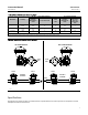
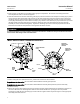
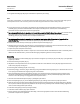
Figure 4. Orientation of the Fisher 2052 Actuator Lever into the Housing and Aligning the Actuator to the Valve Shaft
Markings
UP TRAVEL STOP
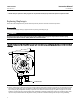
2. Loosen, but do not remove, all casing cap screws and hex nuts (keys 8 and 9). Ensure there is no spring force to the
top casing assembly (key 5). If spring force is detected against the top casing assembly, ensure the up travel stop
cap screw (key 23) is adjusted correctly to prevent over-rotation of the lever (key 14). Refer to figure 3. The travel
indicator screws (key 22) in the end of the lever should be in alignment with the travel scale screws (key 20). If the
up travel stop is confirmed to be adjusted correctly and force is still detected against the top casing assembly,