
Instruction Manual

Instruction Manual
D103296X012
2052 Actuator
November 2011
7
9. Ensure all end play in the valve shaft is removed by directing the valve shaft and control element toward the
actuator as much as possible.
10. Tighten the socket head cap screw (key 15) which compresses the splined lever connection to the valve shaft (see
table 6). Install the cover or plug (key 2) into the access hole in the housing.
CAUTION
When adjusting the travel stop for the closed position of the valve ball or disk, refer to the appropriate valve instruction
manual for detailed procedures. Undertravel or overtravel at the closed position may result in poor valve performance
and/or damage to the equipment.
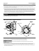
11. Adjusttheuptravelstop(seefigure3)sothatthevalveball or disk is in the desired position. When adjusting the
up travel stop, ensure the stop is not backed out too far, causing the lever to over-rotate. Over-rotation of the lever
may cause damage to valve components. Avoid over-rotation by adjusting the up travel stop so that the travel
indicator screws (key 22) align with the travel scale screws (key 20). See figure 3.
12. Stroke the actuator and adjust the down travel stop so that the valve ball or disk is in the desired position.
Note
Once each travel stop is properly positioned, adequately tighten the hex nut (key 24) to lock the travel stop in place.
13. Make sure that the travel indicator pointer matches the ball or disk position. Remove and install in the proper
position if necessary.
14. Refer to the table of contents for accessory installation procedures.
Maintenance
Actuator parts are subject to normal wear and must be inspected and replaced as necessary. The frequency of
inspection and replacement depends upon the severity of service conditions. Instructions are given below for
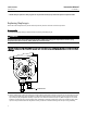
disassembly and assembly of parts. Key numbers referenced in the following steps are shown in figure 7 for the 2052,
except as listed below or otherwise specified in the procedures.
WARNING
Avoid personal injury or property damage from sudden release of process pressure or bursting of parts. Before performing
any maintenance operations:
D Do not remove the actuator from the valve while the valve is still pressurized.
D Always wear protective gloves, clothing, and eyewear when performing any maintenance operations.
D Disconnect any operating lines providing air pressure, electric power, or a control signal to the actuator. Be sure the
actuator cannot suddenly open or close the valve.
D Use bypass valves or completely shut off the process to isolate the valve from process pressure. Relieve process pressure
from both sides of the valve. Drain the process media from both sides of the valve.
D Safely vent the power actuator loading pressure.
D Uselock-outprocedurestobesurethattheabovemeasures stay in effect while you work on the equipment.