
Instruction Manual

Instruction Manual
D103296X012
2052 Actuator
November 2011
4
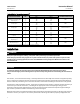
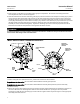
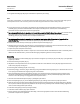
Table 6. Bolting Torque Requirements
(1)
DESCRIPTION KEY NUMBER
ACTUATOR
SIZE
TORQUE
FASTENER LUBRICATION
NSm LbfSft
Rod End Bearing Clamping Bolt
Torque , Key 16
1
2
3
38
180
400
28
130
295
None
End Plate to Housing Bolt
Torque, Key 4
1
2
3
68
120
210
50
90
155
None
Diaphragm Plate to Rod Bolt
Torque, Key 7
1
2
3
27
115
300
20
85
220
Anti-Seize Lubricant
Casing Bolt Torque, Key 8
1
2
3
55
55
55
40
40
40
None
Housing to Yoke Bolt Torque,
Key 28
1
2
3
27
68
245
20
50
180
None
Lever-Spline Clamping Bolt
Torque, Key 15
1
2
3
38
115
175
28
85
130
None
Optional Lockout Kit Mounting
Bolt Torque, Key 53
1
2
3
NA
88
340
NA
65
250
None
1. Exceeding any torque requirements could damage the actuator and impair safe operation.
Installation
WARNING
Always wear protective gloves, clothing, and eyewear when performing any installation operations.
Check with your process or safety engineer for any other hazards that may be present from exposure to process media.
If installing into an existing application, also refer to the WARNING at the beginning of the Maintenance section in this
instruction manual.
CAUTION
To avoid parts damage, do not apply pressure that exceeds the Maximum Diaphragm Casing Pressure in table 1.
Use pressure-limiting or pressure-relieving devices to prevent the Operating Pressure from exceeding the values shown in
table 3.
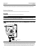
The actuator, as it comes from the factory, is normally mounted on a valve body. If the actuator is shipped separately
or if it is necessary to mount the actuator on the valve, perform the procedures presented in the Actuator Mounting
section. Follow the procedures given i n the valve instruction manual when installing the control valve in the pipeline.
If a positioner is ordered with the actuator, the pressure connection to the actuator is normally made at the factory. If
it is necessary to make this connection, run tubing of the appropriate size for the diaphragm casing pressure
connection (reference table 4) between the pressure connection and the instrument. Keep the length of tubing or
pipe as short as possible to avoid transmission lag in the control signal.
When the control valve i s completely installed and connected to the controlling instrument, check to make sure that
the action is correct (air-to-open or air-to-close) and that the controlling instrument is properly configured for the