
Instruction Manual

Instruction Manual
D103296X012
2052 Actuator
November 2011
16
2. Ensure the actuator lever (key 14) is in the spring-fail position (against the up travel stop).
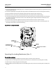
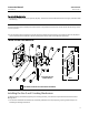
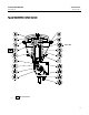
3. Assemble the lockout kit by positioning the locking shaft (key 50) within the center through-hole of the mounting
plate (key 51), as shown in figure 6. Insert the locking pi n (key 52) through the center pinhole of the mounting plate
and through the pin hole in the locking shaft. Install the hairpin cotter pin (key 54) for retention.
4. If installing the lockout kit on an existing actuator, remove the travel indicator (key 21) and travel indicator scale
(key 19) from the actuator by loosening the appropriate s crews.
5. Position the lockout kit against the actuator outboard end. The locking shaft will insert and engage the lever end
geometry.
Size 2 actuator: The standard size 2 lockout kit orientation shown in figure 6 will accommodate the use of
window-mount and end-mount digital valve controllers, positioners, and accessories. This orientation requires
removal of the locking pin in the direction of the bottom side of the actuator.
Size 3 actuator: For the window mounted DVC6200 digital valve controller, the size 3 lockout kit should be oriented
such that locking pin removal is in the direction of the bottom side of the actuator. This mounting plate position
provides necessary clearance with the integral supply pressure regulator. For the end-mount digital valve controller or
accessory option, the size 3 lockout kit should be oriented as shown in the inset picture of figure 6.
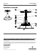
6. Loosely install the four flanged cap screws (key 53). Prior to tightening the fasteners, ensure the through-hole in the
mounting plate is centered around the outside diameter of the locking shaft (key 50). Rotate the assembly by hand
in the appropriate direction opposite of anticipated lever rotation to eliminate initial clearance among parts.
7. Tighten the cap screws (key 53) per the recommended torque values in table 6.
8. Install the travel indicator (key 21) and travel i ndicator scale (key 19) to the lockout parts as illustrated in figure 6.
WARNING
To avoid personal injury or property damage, ensure the travel indicator is installed correctly to coincide with the desired
actuator action. Refer to figure 3 for more information.
9. For normal actuator operation, remove the hairpin cotter pin (key 54) and locking pin (key 52) from the center
pinhole of the mounting plate and reinstall these parts in the second pinhole for storage.
Operating the Locking Mechanism (Size 2 & 3)
To Lock the Actuator
1. With the actuator lever (key 14) against the up travel stop (spring-fail position), insert the locking pin (key 52)
through the center pinhole of the mounting plate and through the pin hole in the locking shaft. Install the hairpin
cotter pin (key 54) for retention.
2. Install the customer-supplied locking device to further prevent removal of the locking pin.
To Unlock the Actuator
1. Remove the customer-supplied locking device.
2. Remove the hairpin cotter pin (key 54) and locking pin (key 52) from the center pinhole of the mounting plate and
reinstall these parts in the second pinhole for storage.
WARNING
To avoid personal injury or property damage, be aware the travel indicator scale (key 19) retains the locking shaft (key 50)
during normal actuator operation. Removal of the travel indicator scale could allow the locking shaft to fall out in certain
actuator orientations.