
Instruction Manual

Instruction Manual
D103296X012
2052 Actuator
November 2011
15
To Unlock the Actuator
1. Remove the padlock. Loosen the jam nut (key 40), and unscrew the threaded bolt until it no longer protrudes inside
the housing.
Note
Ensure the mounting plate assembly bolt is unthreaded far enough that the actuator lever will not contact the bolt during normal
actuator operation.
2. If the mounting plate assembly is to be left partially threaded into the housing, lock it with the jam nut (key 40) so
that it cannot be screwed further into the housing and interfere with normal actuator operation.
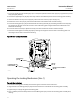
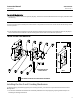
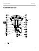
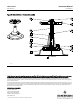
Figure6.Size2and3LockingMechanism
PART ORIENTATION FOR SIZE 3 END-MOUNT INSTRUMENT
CUSTOMER SUPPLIED
LOCKING DEVICE
SIZE 3
Installing the Size 2 and 3 Locking Mechanism
To add the locking mechanism (figure 6) to an existing act uator, purchase the required kit from Emerson Process
Management.
1. The actuator should be mounted to the valve body and both travel stops (key 23) properly positioned prior to
installing the locking mechanism.