
Instruction Manual

Instruction Manual
D103296X012
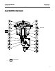
2052 Actuator
November 2011
14
1. Ensure the diaphragm rod assembly (key 10) is in the upward position and the lever (key 14) is against the up travel
stop (spring fail position).
2. Thread the supplied jam nut (key 40) all the way onto the threaded bolt portion of the mounting plate assembly.
3. Loosen the down travel stop hex nut (key 24) and remove the travel stop cap screw (key 23).
4. Remove the vent screen (key 47) from the threaded hole in the bottom of the actuator housing.
5. Secure the locking plate (key 39) to the bottom of the housing assembly by reinstalling the down travel stop (key
23) and hex nut (key 24). Ensure the clearance hole in the locking plate is aligned with the threaded hole in the
bottom of the housing.
6. Ensure the down travel stop is adjusted correctly to achieve the desired actuator rotational output.
7. Install the mounting plate assembly (key 38) by inserting i t through the clearance hole in the locking plate and
threading it into the hole in the actuator housing.
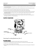
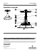
GE51941_A
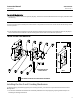
Figure 5. Size 1 Locking Mechanism
LOCKING PLATE
(KEY 39)
MOUNTING PLATE ASSEMBLY
(KEY 38)
JAM NUT
(KEY 40)
CUSTOMER-SUPPLIED
LOCKING DEVICE
Operating the Locking Mechanism (Size 1)
To Lock the Actuator
1. Screw the mounting plate assembly into the housing until it contacts the actuator l ever.
2. Align the hole in the locking plate (key 39) with one of the holes in the disk of the mounting plate assembly.
3. Tighten the jam nut (key 40) against the locking plate.
4. Insert a padlock (not furnished by Emerson Process Management) to prevent the mounting plate assembly from
rotating.