
Brochure


Fisher
®
Cavitation-Control Technologies | 3
Cavitation and Choked Flow
Cavitation is a purely liquid flow phenomena—gases cannot
cavitate. Choked flow may occur as a result of cavitation.
Choked flow occurs when the normal relationship between
flow and increased pressure drop is broken. With choked flow,
an increase in pressure drop by decreasing the downstream
pressure does not result in more flow through the restriction.
Basic valve sizing equations imply that, for a given valve, flow
should continually increase by simply increasing the pressure
differential across the valve. In reality, the relationship given
by these equations holds true for only a limited range. As the
pressure differential is increased, a point is reached where the
flow increase stops. This condition of limited maximum flow is
known as choked flow.
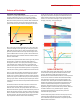
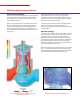
Consider the simple restriction shown to the right. The pressure
of the liquid, P, is plotted as a function of the distance, X,
through the restriction. As a liquid passes through a reduced
cross-sectional area, velocity increases to a maximum and
pressure decreases to a minimum. As the flow exits, velocity is
restored to its original value while the pressure is only partially
restored, thus creating a pressure differential across the device.
There is a point along the flow path called the vena contracta,
where the flow area and pressure are at a minimum and the
velocity is at a maximum. When this point is reached, the local
pressure may drop to or below the vapor pressure of the liquid,
forming vapor cavities. The density of the liquid-vapor mixture
continues to decrease until the compressible choked flow limit
is reached.
The distance from the restriction to the vena contracta will
vary with the pressure conditions and type of restriction.
After the vena contracta, the liquid pressure will recover to or
below the downstream pressure. If the downstream pressure is
higher than the vapor pressure, the vapor cavities will collapse.
This is cavitation. If the downstream pressure stays at or below
the vapor pressure, the vapor cavities do not collapse and the
vapor expansion continues. This is known as flashing.
As the pressure recovers, the vapor cavities implode, forming
high-speed, destructive microjets and localized shock waves.
Either of these mechanisms, when located near the material
surface, can cause severe damage to valve elements such as
the plug, seat, body, and associated pipe.
Science of Cavitation
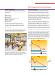
Q, GPM
CHOKED
FLOW
RATE
P CHOKED
C
V
P
The model above depicts mean fluid pressure. Flow through
control valves causes significant deviations from the mean
pressure. Deviations include instantaneous pressure
fluctuations associated with fluid turbulence, and low pressures
in the cores of vortices and eddies associated with boundary-
layer separation, free shear zones, stagnation regions, and
re-entrant zones. These explain some of the differences seen
between the textbook view represented by the blue line and
realistic computational fluid dynamics represented by the
yellow line. These phenomena can produce local pressures
significantly higher or lower than the mean pressure, sufficient
to initiate cavitation in very localized regions. Typically,
cavitation begins before the minimum mean pressure is
reduced to the vapor pressure.
Standard liquid sizing fully accounts for the capacity concern
associated with choked flow and prevents undersizing the
valve. Additional empirical information is required to predict
different levels of cavitation.