
Instruction Manual


Instruction Manual
D102178X012
V260 Valve
September 2012
3
D Check with your process or safety engineer for any additional measures that must be taken to protect against process
media.
D If installing into an existing application, also refer to the WARNING at the beginning of the Maintenance section in this
instruction manual.
D To avoid personal injury or property damage, a minimum of two swivel hoists must be used when lifting NPS 24 CL600
assemblies.
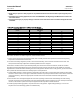
Table 2. Face-to-Face Dimensions and Approximate Weights
VALVE SIZE, NPS
(CL600
(1)
)
FACE-TO-FACE
DIMENSIONS
APPROXIMATE WEIGHT
mm kg
8 661 424
10 788 653
12 840 882
16 990.6 2472
20 1144 4313
24 1397 7257
Inches Pounds
8 26.04 975
10 31.04 1550
12 33.07 2025
16 39.0 5450
20 47.0 9500
24 55.0 16000
1. For CL150 and CL300 valves, face-to-face dimensions are the same as CL600 valves.
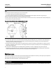
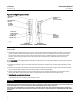
Key number locations are shown in figure 6, unless otherwise noted.
1. Install a three-valve bypass around the c ontrol valve assembly if continuous operation will be necessary during
inspection and maintenance of the valve.
2. The valve is normally shipped as part of a control valve assembly, with an actuator mounted on the valve. The
valve/actuator assembly is adjusted at the factory before the unit is shipped.
If the valve or actuator has been purchased separately or if the actuator has been removed, mount the actuator
according to the Actuator Mounting section and the appropriate actuator instruction manual. Make any necessary
adjustments on the bench before installing the valve in the pipeline. With the valve in the pipeline, you cannot see the
exact position of the ball to determine the fully open or closed positions.
3. Standard flow direction is shown in figure 6. If possible, install the valve in a horizontal pipeline with the drive shaft
horizontal. The actuator can be right- or left-hand mounted in any of the positions shown in the actuator instruction
manual. If necessary, refer to the appropriate actuator instruction manual for installation and adjustment
procedures.
4. Be certain the valve and adjacent pipelines are free of any foreign material that could damage the valve sealing
surfaces. Impurities or entrained solids in the process fluid could plug the passages in the trim. If the process fluid is
not clean, install a filter upstream to keep the pipeline free of impurities or entrained solids.
5. Provideappropriateflangegaskets,andplacethevalveinthepipeline.Tightenflangeboltinginacriss-cross
sequence to ensure the flange gaskets are loaded evenly.